When designing local treatment facilities, which provides for a set of measures to clean up household domestic waste, in the future, we are faced with the disposal of treated wastewater within a given facility, but it is simply necessary to organize the correct site drainage.
Exists a large number of technical solutions on this issue:
- Drainage well;
- Underground pipe-based infiltration fields;
- Modern drainage fields based on structural elements such as drainage tunnels GRAF 300 , drainage blocks GRAF EcoBloc ;
- Drainage trenches;
- Infiltration fields – Silt maps;
- Discharge of purified water after disinfection onto the terrain (ditch, fire reservoir, etc.)
- Vertical type drainage.

Each solution has its own advantages and disadvantages.
Today we will focus on vertical drainage.
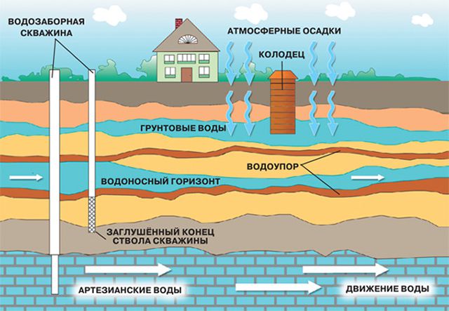
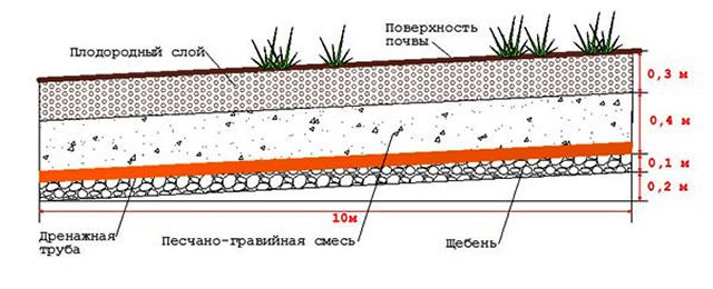
Vertical drainage plot is a set of measures for recycling water (rain, groundwater, after deep biological treatment), followed by infiltration into continental soils. In some cases, such a complex, depending on the geological structure of the soil, solves the problem of drainage and water disposal on the site.
Vertical drainage is used in cases where the site contains soils (clay, loams) with weak infiltrating properties that are not capable of accepting the amount of water that needs to be disposed of. However, if geological exploration is done and at a certain elevation the rock is represented by soils such as coarse-grained, medium-grained, fine-grained sand, which has excellent properties for absorbing water, then there is a chance to divert water from the site at the lowest cost.
Using an example, you can imagine such a picture. Eat personal plot and, according to geological exploration, clay soils are located at the beginning, and at a depth of 8-10 meters there is a sandy layer. However, this layer is located at great depth, which makes access to it difficult. Because of this, a feeling is created that the groundwater level is as high as possible and water can only be disposed of by surface drainage to the terrain (into a roadside ditch, into a ravine, into a forest, etc.).
Another solution could be to dig a deep well using reinforced concrete rings, but this is an expensive procedure that includes the cost of materials, work, transportation costs, and, at the same time, it is not always possible to find a qualified team capable of setting the rings to such a depth. The rings, especially in clayey soils, may become jammed, or the rings, when digging, will begin to shift relative to their axis, which will make installation impossible. There are very few such specialists who take on such work and, even if they do, there is not always a guarantee of success.

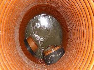
In order not to take risks and spend your financial resources with maximum benefit, another method is used - this is drilling a well with a drilling machine using an auger with a diameter of at least 300 mm. After the installation has drilled the shaft, a special geotextile bag is laid, which, in turn, prevents calmatization (silting) of the crushed stone base. The crushed stone base is a filler for the shaft space, which is an excellent conductor for water. For more efficient operation of such a shaft (drain), a PVC pipe with pre-drilled holes is laid. This design allows you to solve the problem of flooding the site, recycling rainwater and lowering the groundwater level, and can also be used in conjunction with a drainage, sewerage, and rainwater removal system. There may be several such mines, interconnected in one hydraulic complex. For more correct calculations, an accurate analysis of the geological structure of soils is required.
Vertical drains are installed in weak, water-saturated soils to accelerate the consolidation of the foundation by shortening the path of filtration of water squeezed out of the weak layer (Fig. 11.4).
Vertical drains are effective in water-saturated organic and mineral force-compressible soils with a layer thickness of less than 4 m with a filtration coefficient of at least 1 10 -4 m/day.
Vertical drains should be combined with a temporary load that provides the necessary hydraulic gradient and squeeze of pore water from a weak soil layer.
The thickness of the loading layer (with ensured foundation strength) in this case is determined by the requirement to create a pore water pressure, the value of which throughout the entire drained layer at any moment of the estimated consolidation time must be higher than the initial gradient of soil filtration, if the soil has one.
Formula for calculating the thickness of the loading layer

Rice. 11.4.
where y gr, y b - density wet soil used for loading, and water; d e - effective drain diameter; I n - design height of the embankment, m; / 0 - initial gradient of soil filtration taking into account compaction under the weight of the embankment (in the absence of laboratory data, it is taken equal to 2 for peat; for silt and clay - 5).
Vertical drains can be round sandy or flat from synthetic materials.
Sand drains are made in the form of wells filled with sand. The diameter of the wells can be taken from 40 to 60 cm, taking into account the technical parameters of the equipment used. To fill vertical drains, sand with a filtration coefficient of at least 6 m/day is used. The efficiency of vertical drains is significantly increased by adding 5-18% (by weight) lime to the filling material. When using vertical drains, the embankment or its bottom part a thickness of at least 50 cm should be constructed from draining soils with a filtration coefficient of at least 3 m/day.
Depending on the permeability of the soil and the required time for completion of the intensive part of the settlement, the distance between the drains may vary (2-4.5 m).
When designing a subgrade with vertical drains, the required distance between them is determined by calculation based on the specified period for achieving the intensive part of the settlement of soft soil.
To calculate foundations with vertical drains, the following initial data are required:
- results of compression and consolidation tests of thin soils;
- calculated thickness of the weak layer;
- calculated values of load and final settlement of weak strata.
The required degree of consolidation of a weak foundation and the period for its achievement are set taking into account the capital nature of the road pavement and the deadline for completing the filling of the roadbed established by the construction organization project.
To calculate a foundation with vertical drains, the distance between the drains is pre-assigned. Next, the correctness of this assignment is checked. The degree of consolidation of the base with vertical drains is determined by the formula
Where U B - the degree of consolidation of the base during vertical filtration of water from the base; U r- the same with horizontal filtration of water (to drains).
Quantities U B and ^set according to graphs (Fig. 11.5).
The time factor required to determine /7 V is calculated using the formula

where C in is the consolidation coefficient for vertical filtration; Yaf - design path of vertical water filtration; Gtr - required consolidation period.
Time factor required to determine Ur, determined by the formula

Where C g- coefficient of soil consolidation during horizontal filtration; / - distance between drains.

0,01 0,02 0,03 0,06 0,08 0,1 0,2 0,3 0,6 0,8 1
Time factor T g
Rice. 11.5. Graphs for determining the degree of consolidation of foundation soil with vertical drains:
A- with vertical filtration; b - with horizontal filtering (i = l/d, where / is the distance between drains, d- drain diameter)
If, with the prescribed distance between drains, the required reduction in consolidation time cannot be achieved, then the drain spacing is reduced and the calculation is repeated.
Flat belt drains are strips of geotextile with a plastic core inside, 10 cm wide. Flat drains are calculated using the above method. The step between drains is taken according to the calculation depending on the properties of soft soil and the required consolidation time within 1-2 m.
Vertical drainage systems are used to reduce the water level in the soil, which protects buildings and structures from deformation and destruction due to uneven shrinkage.
There are several types of vertical drainage:
- systematic. Water intake wells are evenly spaced in the corners of a triangular or square grid;
- selective. Drainage wells are installed only in some excessively moist places;
- coastal. Comprises linear system
- water collectors that protect the territory from flooding from reservoirs, rivers, lakes, etc.; combined.
This is a combination of vertical wells with a horizontal drainage system.
Purpose of vertical drainage
Using the system, the groundwater level is regulated. The territory is protected from the penetration of water flows from lakes, rivers, and reservoirs. A vertical drainage network is used to reduce the pressure of groundwater and reduce its influx into the drained formation from deep horizons.
System structure
A deep bore well is made, reaching the aquifer and completely or partially cutting through it. The depth of the well is determined depending on the hydrogeological conditions, the geological structure of the soil and the water level. Wells are deepened to 5-50 meters or more, have a diameter of 0.7-1 meter, and their walls are reinforced with casing pipes. When liquid enters a vertical well, the groundwater level decreases and a depression funnel is formed. It can be symmetrical or asymmetrical. The water intake part of the well is equipped with filters made of round perforated pipes, sprinkled around the perimeter with crushed stone and sand of different fractions.
- The cost of network installation is reduced, there is no need to use expensive special equipment, and the labor intensity of the work is reduced.
- The terrain is preserved, trees are not required to be cut, and installation is possible around various obstacles.
- Wiring drainage system SoftRock is more effective across the area due to the comprehensive removal of excess water.
- Modern drainage does not require special care and maintenance, and does not silt up, unlike vertical wells.
Contact the company's specialists to receive detailed advice on choosing a SoftRock system for specific operating conditions.
A drainage system in a private courtyard will avoid many problems with both buildings and the quality of the soil for the beds. Its design is the right decision of the owner in any case. But, the relevance of such a system is especially acute if the house has recessed parts. In such a situation, drainage around the house is effective tool protection against flooding, which is caused by large amounts of precipitation and rising groundwater levels.
Important! According to SNiP 2.06.14-85, SNiP II-52-74, it is mandatory to install a drainage system near buildings with a significant depression, in areas with clay soil, in areas with high occurrence of groundwater aquifers, in areas located at the bottom of the slope.
Please note that the above standards are relevant for both industrial facilities and residential buildings.
What the market offers: types of drainage
Initially, please note that the drainage system is arranged according to certain rules and technologies. Depending on the tasks assigned to it, drainage can be:
- wall (vertical);
- ring (trench).
Option No. 1 Open drainage: description of the device
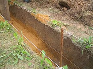
To drain the area, a custom ditch can be used, dug according to a certain algorithm. In principle, everything is more than simple: a drainage ditch up to half a meter wide and 0.7 meters deep is dug along the perimeter of the site. From it, water is discharged into the waste basin. Such an object can be common to several nearby households.
Important! The drainage ditch should have a slope of 30 degrees in relation to the collection point for diverted wastewater. Therefore, even at the stage of digging a ditch for clay soil For each linear meter you need to make a slope of 2 cm, and for sand - 3 cm.

We would like to note right away that such indicators must be met for open drainage, and for a closed system, which will be discussed further.
Option No. 2 Closed drainage: two technologies
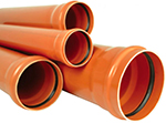
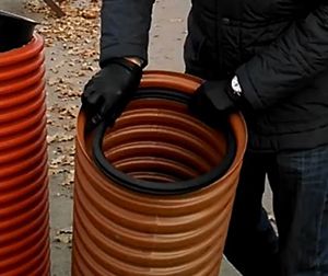
- Closed drainage around a private house involves not only digging a ditch, but also installing a pipeline through which unnecessary moisture enters drainage wells. From an economic point of view, it is most profitable to construct such a pipeline system from PVC pipes. The most popular diameters: 63 mm, 110 mm. Moreover, it is important that the inner surface of the pipes is smooth and the outer surface is corrugated. The drainage pipeline also has holes along its entire length to protect it from soil and sand particles; it is covered in coconut fabric or geotextile material.
- A closed system for draining the area can be implemented in another way. It is very similar to the pipeline solution, but instead of laying pipes, a special water drainage channel is formed. A trench dug at a slope is half filled with coarse stone material - broken bricks, gravel, crushed stone. The second layer is the same materials, but of a finer fraction; soil is already poured on top. This technology has one serious drawback - siltation. Experts recommend eliminating it by laying an additional filter layer from the same geotextile or tecton.

Important! If closed drainage is arranged correctly, then the groundwater level does not rise above the point that is calculated in advance. At the same time, soil fertility increases.
Option No. 3 Vertical drainage
Wall drainage, as you might guess from the name, is designed to protect buildings from moisture. There is virtually no alternative to it in low-lying areas, since only such a system will once and for all eliminate questions regarding flooding of the basement floor during rainstorms or spring melting of snow.
The vertical drainage device looks like this in stages:
- A pit is dug around the perimeter of the building, the bottom of which is covered with a sand cushion. The depth of drainage around the house is determined by the height of the foundation, but in any case the recess will be 30 centimeters below the base of the structure.
- Using a laser level, measures are taken to eliminate existing differences in height and a slope is formed directed towards the drainage collector.
- The ditch is covered with geotextiles.
- The slope is checked.
- A layer of well-washed gravel is poured, making sure that the fraction is larger than the holes in the pipe. Otherwise, a problem such as blockages is guaranteed.
- Recesses are formed for laying the drainage pipeline.
- Pipe installation is in progress.
- At each turn, a vertical pipe is mounted, protected from above by a lid. In this way, channels are provided through which the wall drainage system is periodically maintained, which makes it possible to operate it effectively for many years.
- The fully installed system will be carefully checked again to ensure the correct slope.
- The drainage pipeline is wrapped with geotextile, very tightly and secured using a thin nylon cord.
- A layer of gravel 20 cm thick is poured on top.
- Another layer of geotextile is laid.
- Next comes a layer of river sand and soil.

We would like to emphasize that if the location of the site is characterized by complex hydrogeological conditions, then the optimal combination will be: vertical drainage + linear. This point is very important to take into account when deciding how to make drainage around the house yourself.
Important! Clause 5.23 of SNiP 2.06.14-85 reflects the standards for linear and trenchless drainage. According to them, preference is given to any system based on economic feasibility. In the event that the choice fell on open system, the depth of the ditch must be at least 4 meters. In addition, it is necessary to focus on the depth of soil freezing in a particular area.
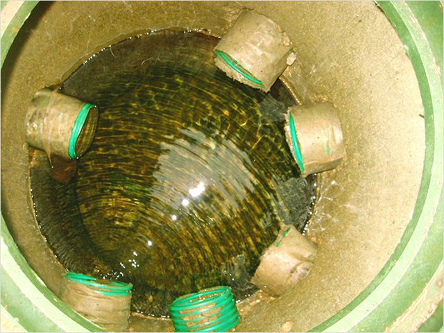
Prefabricated drainage well
The place where drainage water is discharged can be not only a collection pool, but also a well. It can be quickly built from reinforced concrete rings, although, as an option, the walls are made of solid castings. This will require a reinforcing mesh and a cement-based mortar. In the place where pipes coming from different directions intersect, soil is selected, walls are formed, and a drainage cushion is placed at the bottom. Before you start backfilling, you need to carry out thermal insulation measures - foam plastic with a thickness of 25 cm is used.
Local drainage device
It happens that a nuisance in the form of constantly collecting water occurs only in a certain place on the site. Modern construction technologies in this regard offer a way to solve the problem, such as local drainage. It is not difficult to build an object of this type:
- A closed container or a special water intake is buried in the ground. In any case, the possibility of using accumulated water for economic purposes must be provided.
- If water stagnates at the border local area, then it is simply taken to the street through a drainage ditch. In this case, installation of a water intake is not required.
You can't build without a project
So, we hope you have become familiar with the upcoming scope of work, and along the way, have figured out which of the described systems is suitable in your particular case. However, there is no point in cutting from the shoulder and first you need to develop a project for the future system. Do not ignore this stage, even if there is a need to set up a small local facility.
Important! Clause 5.20 of SNiP 2.06.14-85 states that when designing drainage, priority should be given to gravity systems. Drainage with forced pumping requires convincing justification.
The drainage project consists of:
- Schematic images of sections of the system laying - sketches.
- The calculation part indicating croquet numbers regarding the slope, dimensions of ditches, pipe sections, distances of the relative positions of the structural parts of the system.
- Indications of standard sizes of drains, wells, connecting units, etc.
It is impossible to competently draw up a project without possessing the following data:
- Average precipitation for the year.
- Features of the local landscape.
- Soil composition.
- Indicator of groundwater level.
- How close is the nearest body of water?
What materials can be used?
We decided to highlight this issue for consideration separately, since it is of most concern to non-professional craftsmen who have decided to independently install drainage around the house.

The modern market is ready to satisfy consumers with any wallet. So, the drainage pipeline can be made up of pipes:
- polyvinyl chloride;
- reinforced concrete;
- ceramic;
- concrete.
Also, pipe filters made of porous concrete or polymer concrete can be used as consumables.
In conclusion: about preparing the foundation for drainage installation
Before proceeding with the installation of wall drainage, it is necessary to prepare the foundation in a certain way. To do this, you will need bitumen-kerosene mastic - applied to the foundation from the outside. While this coating is still wet, we fix a special reinforcing mesh (possibly plaster and paint mesh) - cell size 2 x 2 mm. After the mastic has hardened, about 24 hours later, working surface once again coated with bitumen compound.
If you ask any experienced builder, developer, or landscape designer about what needs to be done, first of all, on a newly acquired and not yet developed plot, the answer will be unequivocal: the first thing is drainage, if there is a need for it. And such a need almost always happens. Drainage of a site is always associated with a very large volume of excavation work, so it is better to do it right away, so as not to disturb the beautiful landscape that any good owners arrange on their property.
Of course, the easiest way is to order site drainage services from specialists who will do everything quickly and correctly, using special equipment. However, this will always come at a cost. Perhaps the owners did not plan for these expenses; perhaps they will violate the entire budget planned for the construction and improvement of the site. In this article, we propose to consider the question of how to do the drainage of a site with your own hands, as this will allow you to save a lot of money, and in most cases it is quite possible to do this work yourself.

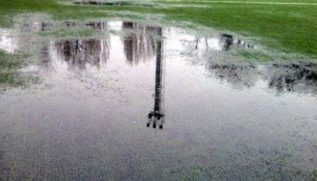
Looking through estimates and price lists related to site drainage, some developers begin to doubt the feasibility of these measures. And the main argument is that before, in principle, no one “bothered” much with this. With this argument for refusing to drain the site, it is worth noting that the quality and comfort of human life has greatly improved. No one wants to live in dampness or in a house with earthen floors. No one wants to see cracks on their home, blind areas and paths that appear after another cold season. All homeowners want to improve their property or, to put it in a modern and fashionable way, to make landscape design. After the rain, no one wants to “knead mud” in stagnant puddles. If this is the case, then drainage is definitely needed. You can do without it only in very rare cases. We will explain in what cases a little later.
Drainage? No, I haven't heard...
Drainage is nothing more than the removal of excess water from the surface of a site or from the depths of the soil. Why is site drainage needed?
- First of all, in order to remove excess water from the foundations of buildings and structures. The appearance of water in the area of the base of the foundation can provoke either soil movement - the house will “float”, which is typical for clay soils, or in combination with freezing, frost heaving forces may appear, which will create efforts to “squeeze” the house out of the ground.

- Drainage is designed to remove water from basements and basements. No matter how effective the waterproofing is, excess water will still seep through the building structures. Basements in homes without drainage can become damp, which can encourage the growth of mold and other fungi. In addition, precipitation in combination with salts present in the soil very often form aggressive chemical compounds that negatively affect building materials.

- Drainage will prevent the septic tank from being “squeezed out” when the groundwater level is high. Without drainage, a wastewater treatment system will not last long.
- Drainage together with the system and around buildings ensures rapid removal of water, preventing its seepage to the underground parts of buildings.
- Drainage prevents the soil from becoming waterlogged. In areas equipped with properly planned and constructed drainage, water will not stagnate.
- Waterlogged soil can cause plant roots to rot. Drainage prevents this and creates conditions for the growth of all garden, vegetable and ornamental plants.
- With heavy rainfall in areas that have a slope, the fertile layer of soil can be washed away by streams of water. Drainage directs water flows into the drainage system, thereby preventing soil erosion.

Water erosion of fertile soil in the absence of drainage is a serious problem in agriculture
- If the site is surrounded by a fence built on a strip foundation, then it can “seal” natural water drainage routes, creating conditions for waterlogging of the soil. Drainage is designed to remove excess water from the perimeter of the site.
- Drainage helps avoid the formation of puddles on platforms, sidewalks and garden paths.
When drainage is necessary anyway
Let's consider those cases when drainage is needed in any case:
- If the site is located on flat terrain, then drainage is required, since if there is a large amount of precipitation or snow melts, the water will simply have nowhere to go. According to the laws of physics, water always goes under the influence of gravity to a lower place, and on a flat landscape it will intensively saturate the soil in a downward direction, which can lead to waterlogging. So, from a drainage point of view, it is beneficial for the site to have a slight slope.
- If the site is located in a lowland, then drainage is definitely needed, since water will flow from higher places to those located below.
- Areas with a strong slope also require drainage, since quickly flowing water will erode the top fertile layers of the soil. It is better to direct these flows into drainage channels or pipes. Then the bulk of the water will flow through them, preventing the soil layer from being washed away.
- If the site is dominated by clay and heavy loamy soils, then after precipitation or melting snow, water will often stagnate on them. Such soils prevent its penetration into the deeper layers. Therefore, drainage is required.
- If the groundwater level (GWL) in the area is less than 1 meter, then drainage cannot be avoided.
- If the buildings on the site have a deeply buried foundation, then there is a high probability that its base will be in the zone of seasonal rise of groundwater. Therefore, it is necessary to plan drainage at the stage of foundation work.
- If a significant part of the site area is covered with artificial surfaces made of concrete, paving stones or paving slabs, and also if there are lawns equipped with an automatic watering system, then drainage is also needed.
From this impressive list, it becomes clear that drainage to one degree or another is necessary in most cases. But before planning and doing it, you need to study the site.
Studying the site for topography, soil type and groundwater level
Each site is individual in terms of topography, soil composition and groundwater level. Even two areas located nearby can be very different from each other, although there will still be a lot in common between them. Modern requirements for construction suggest that the design of a house should begin only after geological and geodetic surveys have been carried out with the preparation of special reports, which will indicate a lot of data, most of which is understandable only to specialists. If we “translate” them into the language of ordinary citizens who do not have an education in the field of geology, hydrogeology and geodesy, then they can be listed as follows:
- Topographic survey of the area where it is proposed. The photographs must indicate the cadastral boundaries of the site.
- Characteristics of the relief, which should indicate what type of relief is present on the site (undulating or flat). If there are slopes, then their presence and direction are indicated; it is in their direction that the water will flow. Attached is a topographic plan of the site indicating the relief contours.

- Characteristics of the soil, what type of soil it is and at what depth it lies on the site. To do this, specialists drill exploration wells in different places on the site, from where they take samples, which are then examined in the laboratory.
- Physico-chemical properties of soil. Its ability to be load-bearing for the planned house, as well as as soil in combination with water, will affect concrete, metal and other building materials.
- The presence and depth of groundwater, their seasonal fluctuations, taking into account exploration, archival and analytical data. It is also indicated in which soils water can appear and how they will affect the planned building structures.
- The degree of soil heaving, the possibility of landslides, subsidence, flooding and swelling.
The result of all these studies should be recommendations on the design and depth of the foundation, the degree of waterproofing, insulation, protection from aggressive chemical compounds, drainage. It happens that on a seemingly impeccable plot of land, specialists will not allow you to build the house that the owners intended. For example, a house with a basement was planned, and the high ground level forces experts to recommend against doing this, so instead of the originally planned strip foundation with a basement they will recommend a pile floor without underground premises. There is no reason not to trust these studies and specialists, since they have indisputable tools in their hands - measurements, drilling, laboratory experiments, statistics and calculations.

Of course, geological and geodetic surveys are not done for free, they are done at the expense of the developer and are required on a new site. This fact is often the subject of indignation by some owners, but it is worth understanding that this procedure will help save a lot of money during the construction and further operation of the house, as well as when maintaining the site in good condition. Therefore, this seemingly unnecessary and expensive bureaucracy is necessary and very useful.
If a plot of land is purchased with existing buildings that have been in use for at least several years, then you can also order geological and geodetic surveys, but you can do without them and learn about groundwater, its seasonal rise and the unpleasant impact on human life based on other signs. Of course, this will come with a certain amount of risk, but in most cases it works. What you should pay attention to?
- First of all, this is communication with the former owners of the site. It is clear that it is not always in their interests to talk in detail about problems with flooding, but, nevertheless, you can always find out whether any drainage measures have been taken. They will not hide this for anything.
- An inspection of the basement can also tell a lot. Regardless of whether cosmetic repairs were made there. If there is a high level of humidity in the premises, it will be immediately felt.

- Meeting your neighbors and interviewing them can be much more informative than communicating with the former owners of the property and house.
- If there are wells or boreholes on your property and on your neighbors’ property, then the water level in them will eloquently indicate the groundwater level. Moreover, it is advisable to observe how the level changes in different seasons. Theoretically, the water should rise to its maximum in the spring after the snow has melted. In summer, if there have been dry periods, the groundwater level should drop.
- Plants growing on a site can also “tell” a lot to the owner. The presence of plants such as cattail, rush, sedge, horse sorrel, nettle, hemlock, and foxglove indicate that groundwater are at a level of no more than 2.5-3 meters. If even during a drought these plants continue their rapid growth, this once again indicates the proximity of water. If licorice or wormwood grow on the site, then this is evidence that the water is at a safe depth.

- Some sources talk about the old way determining the groundwater level that our ancestors used before building a house. To do this, a piece of turf was removed from the area of interest and a shallow hole was dug, a piece of wool was placed at the bottom, an egg was placed on it, and an inverted egg was placed on top. clay pot and removed turf. After dawn and sunrise, they removed the pot and watched as the dew fell. If the egg and wool are covered in dew, then the water is shallow. If dew has fallen only on the wool, then there is water, but it is at a safe depth. If both the egg and the wool are dry, then the water is very deep. It may seem that this method is akin to quackery or shamanism, but in fact there is an absolutely correct explanation for it, from the point of view of science.
- The growth of bright grass in the area even during a drought, as well as the appearance of fog in the evening hours, indicates the proximity of groundwater.
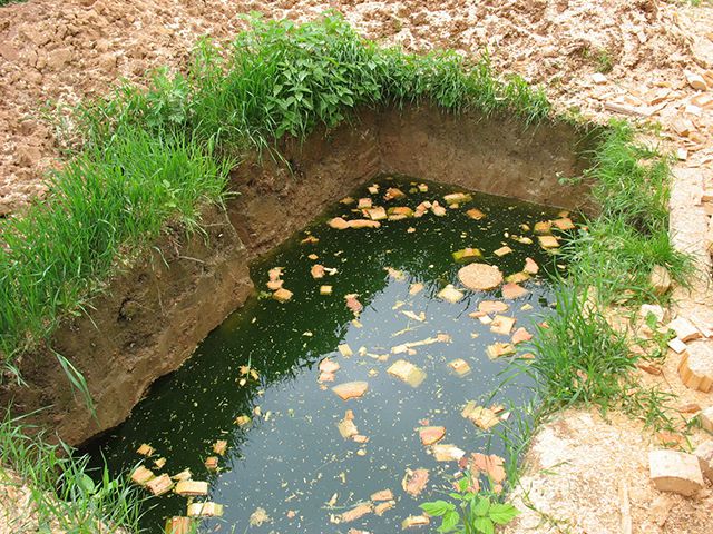
- The most the best way Independent determination of groundwater level on the site is the drilling of test wells. To do this, you can use a regular garden auger with extensions. It is better to drill during the highest water rise, that is, in the spring after the snow melts. First of all, wells should be made at the site of construction of a house or an existing structure. The well must be drilled to the depth of the foundation plus 50 cm. If water begins to appear in the well immediately or after 1-2 days, this indicates that drainage measures are required.

A beginner's research geologist's kit - a garden auger with an extension cord
- If puddles stagnate in the area after rain, this may indicate the proximity of groundwater, as well as the fact that the soil is clayey or heavy loamy, which prevents water from going deeper normally. In this case, drainage is also necessary. It will also be very useful to update the fertile soil to a lighter one, then there will be no problems with growing most garden and garden plants will not be.
Even a very high groundwater level in the area, although big problem, but the problem can be completely solved with the help of well-calculated and well-executed drainage. Let's give good example– more than half of the territory of Holland lies below sea level, including the capital – the famous Amsterdam. The groundwater level in this country can be several centimeters deep. Those who have been to Holland have noticed that after rain there are puddles there that are not absorbed into the ground, since there is simply nowhere for them to be absorbed. However, in this cozy country, the issue of land drainage is being resolved through a set of measures: dams, dikes, polders, locks, and canals. In Holland there is even a special department, Waterschap, which deals with flood protection. The abundance of windmills in this country does not mean that they grind grain. Most mills are involved in pumping water.

We do not at all encourage you to specifically purchase a plot of land with high level groundwater, on the contrary, this should be avoided by everyone possible ways. And the example of Holland was cited only so that readers could understand that there is a solution to any problem with groundwater. Moreover, in most of the territory of the former USSR settlements and holiday villages are located in areas where groundwater levels are within acceptable limits, and seasonal rises can be dealt with independently.
Types of drainage systems
There are a great variety of drainage systems and their varieties. Moreover, in different sources, their classification systems may differ from each other. We will try to talk about the simplest, from a technical point of view, drainage systems, but at the same time effective, which will help solve the problem of removing excess water from the site. Another argument in favor of simplicity is that the fewer elements any system has and the more time it can operate without human intervention, the more reliable it will be.
Surface drainage
This type of drainage is the simplest, but nevertheless quite effective. It is intended mainly for draining water coming in the form of precipitation or melting snow, as well as for draining excess water in case of any technological processes, for example, when washing cars or garden paths. Surface drainage is done in any case around buildings or other structures, areas, exit points from a garage or yard. Surface drainage comes in two main types:
- Point drainage designed to collect and drain water from a specific place. This type of drainage is also called local drainage. The main locations for point drainage are under roof gutters, in pits in front of doors and garage doors, in the locations of watering taps. In addition to its direct purpose, point drainage can complement another type of surface drainage system.
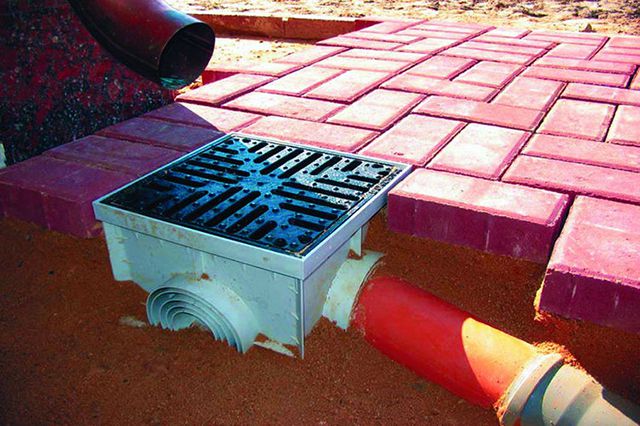
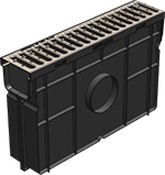
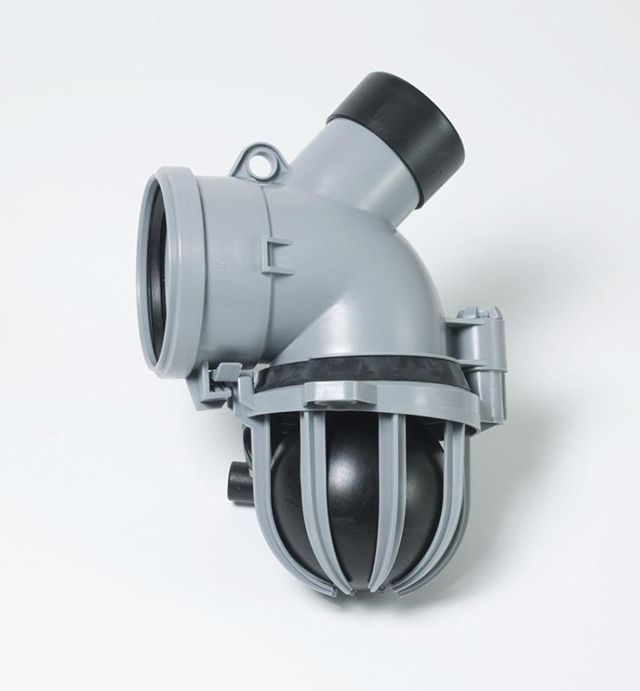
Storm water inlet is the main element of point surface drainage
- Linear drainage needed to remove water from a larger area compared to a single point. It represents a collection trays And channels, mounted with a slope, equipped with various elements: sand traps (sand traps), protective grilles , performing filtering, protective and decorative functions. Trays and channels can be made from the most different materials. First of all, it is plastic in the form of polyvinyl chloride (PVC), polypropylene (PP), polyethylene low pressure(PND). Materials such as concrete or polymer concrete are also widely used. Grates are most often used in plastic, but in areas where increased load is expected, products made of stainless steel or even cast iron can be used. Work on organizing linear drainage requires concrete preparation of the base.

It is obvious that any good surface drainage system almost always combines elements of point and linear. And they all come together into common system drainage, which may also include another subsystem, which we will consider in the next section of our article.
Deep drainage
In most cases, surface drainage alone cannot be done. To solve the problem qualitatively, we need another type of drainage - deep, which is a system of special drainage pipes (drains) , laid in those places where it is necessary to lower the groundwater level or divert water from the protected area. Drains are laid with a slope to the side collector, well , artificial or natural reservoir on the site or beyond. Naturally, they are laid below the level of the base of the foundation of the protected building or along the perimeter of the site at a depth of 0.8-1.5 meters to lower the groundwater level to non-critical values. Drains can also be laid in the middle of the site at a certain interval, which is calculated by specialists. Typically, the interval between pipes is 10-20 meters, and they are laid in the form of a herringbone, directed towards the main outlet pipe-collector. It all depends on the groundwater level and its quantity.

When laying drains in trenches, it is imperative to take advantage of all the features of the site’s topography. Water will always flow from a higher place to a lower place, so drains are laid the same way. It is much more difficult if the area is absolutely flat, then the required slope is given to the pipes by adding a certain level to the bottom of the trenches. It is customary to make a slope of 2 cm per 1 meter of pipe for clay and loamy soils and 3 cm per 1 meter for sandy soils. Obviously, with sufficiently long drains, it will be difficult to maintain the required slope on a flat area, since for 10 meters of pipe the level difference will already be 20 or 30 cm, so a necessary measure is to organize several drainage wells that will be able to receive the required volume of water.
It should be noted that even with a smaller slope, water, even at 1 cm per 1 meter or less, will still, obeying the laws of physics, try to go lower, but the flow rate will be less, and this can contribute to silting and clogging of drains. And any owner who has laid sewer or drainage pipes at least once in his life knows that maintaining a very small slope is much more difficult than a large one. Therefore, you should not be “embarrassed” in this matter and feel free to set a slope of 3, 4 and even 5 cm per meter of drainage pipe, if the length and planned difference in depth of the trench allows.
Drainage wells are one of the most important components of deep drainage. They can be of three main types:
- Rotary wells – arranged where drains make a turn or where several elements are connected. These elements are needed for inspection and cleaning of the drainage system, which must be done periodically. They can be either small in diameter, which will only allow cleaning and rinsing with a stream of water under pressure, but they can also be wide, which provide human access.

- Water intake wells – their purpose is absolutely clear from their name. In those areas where it is not possible to drain water into depth or beyond, it becomes necessary to collect water. This is exactly what these wells are designed for. Previously, they were mainly a structure made of monolithic concrete, concrete rings or plastered cement mortar bricks Now most often used plastic containers of various volumes, which are protected from clogging or silting by geotextiles and crushed stone or gravel. Water collected in the intake well can be pumped outside the site using special submersible drainage pumps, can be pumped out and transported by tanker trucks, or can settle in a well or pool for further irrigation.
- Absorption wells designed to drain water if the topography of the site does not allow moisture to be removed beyond its boundaries, but the underlying soil layers have good absorbency. Such soils include sandy and sandy loam. Such wells are made with large diameters (about 1.5 meters) and depths (at least 2 meters). The well is filled with filter material in the form of sand, sand-gravel mixture, crushed stone, gravel, broken brick or slag. To prevent eroded fertile soil or various blockages from entering from above, the well is also covered with fertile soil. Naturally, the side walls and bottom are protected with sprinkling. Water entering such a well is filtered by its contents and goes deep into sandy or sandy loam soils. The ability of such wells to remove water from the site may be limited, so they are installed when the expected throughput should not exceed 1-1.5 m 3 per day.

Of the drainage systems, the main and most important is deep drainage, since it is it that provides the necessary water regime for both the site and all the buildings located on it. Any mistake in the design and installation of deep drainage can lead to very unpleasant consequences, which can lead to the death of plants, flooding of basements, destruction of house foundations, and uneven drainage of the area. That is why it is recommended not to neglect geological and geodetic research and order a drainage system design from specialists. If it is possible to correct flaws in surface drainage without severely disturbing the landscape of the site, then with deep drainage everything is much more serious, the cost of an error is too high.
Overview of components for drainage systems
To independently carry out the drainage of the site and the buildings located on it, you need to find out what components will be required for this. From the widest selection of them, we tried to show the most used ones at present. If previously the market was dominated by Western manufacturers who, as monopolists, dictated high prices for their products, now sufficient quantity domestic enterprises offer their products, which are in no way inferior in quality.
Surface Drainage Parts
The following parts can be used for point and linear surface drainage:
| Image | Name, manufacturer | Purpose and description | |
|---|---|---|---|
| Concrete drainage tray 1000*140*125 mm with stamped galvanized steel grating. Production - Russia. | Designed for surface water drainage. Capacity 4.18 l/sec, can withstand loads of up to 1.5 tons (A15). | 880 rub. | |
| Concrete drainage tray with cast iron grate, dimensions 1000*140*125 mm. Production - Russia. | The purpose and capacity are the same as in the previous example. Capable of supporting loads up to 25 tons (C250). | 1480 rub. | |
| Concrete drainage tray with galvanized steel mesh grating, dimensions 1000*140*125 mm. Production - Russia. | The purpose and capacity are the same. Capable of supporting loads up to 12.5 tons (B125). | 1610 rub. | |
| Polymer concrete drainage tray 1000*140*70 mm with a plastic grid. Production - Russia. | The purpose is the same, throughput 1.9 l/sec. Capable of withstanding loads up to 1.5 tons (A15). The material combines the advantages of plastic and concrete. | 820 rub. | |
| Polymer concrete drainage tray 1000*140*70 mm with cast iron grate. Production - Russia. | The throughput is the same. Capable of withstanding up to 25 tons of load (C250). | 1420 rub. | |
| Polymer concrete drainage tray 1000*140*70 mm with steel mesh grating. Production - Russia. | The throughput is the same. Capable of withstanding up to 12.5 tons of load (B125). | 1550 rub. | |
| Plastic drainage tray 1000*145*60 mm with a galvanized stamped grid. Production - Russia. | Made from frost-resistant polypropylene. Flow rate 1.8 l/sec. Capable of withstanding loads up to 1.5 tons (A15). | 760 rub. | |
| Plastic drainage tray 1000*145*60 mm with cast iron grate. Production - Russia. | Flow rate 1.8 l/sec. Capable of supporting loads up to 25 tons (C250). | 1360 rub. | |
| Complete plastic storm water inlet (siphon-partitions 2 pcs., waste basket – 1 pc.). Size 300*300*300 mm. With plastic grille. Production - Russia. | Designed for point drainage of water flowing from the roof through a drainpipe, and can also be used to collect water under courtyards and gardens watering taps. Can be connected to shaped parts with diameters of 75, 110, 160 mm. Removable basket allows for quick cleaning. Withstands loads up to 1.5 tons (A15). | For a set including siphon partitions, a waste collection basket and a plastic grill - 1000 rubles. | |
| Complete plastic storm water inlet (siphon-partitions 2 pcs., waste basket – 1 pc.). Size 300*300*300 mm. With cast iron grate “Snowflake”. Production - Russia. | The purpose is similar to the previous one. Withstands loads up to 25 tons (C250). | For a set including siphon partitions, a waste collection basket and a cast iron grate - 1,550 rubles. | |
 | The sand trap is plastic with a galvanized steel grid. Dimensions 500*116*320 mm. | Designed to collect dirt and debris in surface linear drainage systems. It is installed at the end of a line of gutters (trays) and is subsequently connected to the pipes of the storm sewer system with a diameter of 110 mm. Capable of withstanding loads up to 1.5 tons (A15). | For a set including grilles 975 rubles. |
In the table we intentionally showed trays and storm water inlets Russian production, made from materials different from each other and having different configurations. It is also worth noting that the trays have different widths and depth and, accordingly, their throughput is also not the same. There are a lot of options for the materials from which they are made and sizes; there is no need to list them all, since it depends on many factors: the required throughput, the expected load on the ground, the specific implementation scheme of the drainage system. That is why it is best to entrust drainage system calculations to specialists who will calculate the required size, quantity, and select components.
There was absolutely no need to talk about possible components for drainage trays, rain inlets and sand traps in the table, since in each individual case they will be different. When purchasing, if there is a system design, the seller will always suggest the ones you need. They can be end caps for trays, fastenings for gratings, various corner and transition elements, reinforcing profiles and others.

A few words should be said about sand traps and storm water inlets. If surface linear drainage around the house is implemented with rainwater inlets in the corners (and this is usually done), then sand traps will not be required. Stormwater inlets with siphon partitions and waste baskets perform their role perfectly. If the linear drainage does not have storm inlets and goes into a sewer drainage pipe, then a sand trap is required. That is, any transition from drainage trays to pipes must be done either using a storm inlet or a sand trap. Only this way and no other way! This is done to ensure that sand and various heavy debris do not get into the pipes, as this can lead to their rapid wear, and over time both they and the drainage wells will become clogged. It is difficult to disagree with the fact that it is easier to periodically remove and wash the baskets while on the surface than to go down into the wells.

Surface drainage also includes wells and pipes, but they will be discussed in the next section, since, in principle, they are the same for both types of systems.
Details for deep drainage
Deep drainage is more complex engineering system, requiring more parts. In the table we present only the main ones, since all their diversity will take up a lot of space and attention of our readers. If you wish, it will not be difficult to find catalogs of manufacturers of these systems and select the necessary parts and components for them.
| Image | Name and manufacturer | Purpose and description | Approximate price (as of October 2016) |
|---|---|---|---|
| Drainage pipe with a diameter of 63 mm made of HDPE, corrugated, single-walled, in a geotextile filter. Manufacturer: Sibur, Russia. | Designed to remove excess moisture from foundations and areas. Wrapped with geotextile to prevent clogging of pores with soil and sand, which prevents clogging and silting. They have full (circular) perforation. Made from low-density polyethylene (HDPE). Hardness class SN-4. Laying depth up to 4 m. | For 1 m.p. 48 rub. | |
| Drainage pipe with a diameter of 110 mm made of HDPE, corrugated, single-walled, in a geotextile filter. Manufacturer: Sibur, Russia. | similar to above | For 1 m.p. 60 rub. | |
| Drainage pipe with a diameter of 160 mm made of HDPE, corrugated, single-walled, in a geotextile filter. Manufacturer: Sibur, Russia. | similar to above | For 1 m.p. 115 rub. | |
| Drainage pipe with a diameter of 200 mm made of HDPE, corrugated, single-walled, in a geotextile filter. Manufacturer: Sibur, Russia. | similar to above | For 1 m.p. 190 rub. | |
| Single-wall corrugated HDPE drainage pipes with a coconut coir filter with diameters of 90, 110, 160, 200 mm. Country of origin: Russia. | Designed for drainage excess moisture from foundations and areas on clayey and peat soils. Coconut coir has increased reclamation properties and strength compared to geotextiles. They have circular perforation. Hardness class SN-4. Laying depth up to 4 m. | 219, 310, 744, 1074 rub. for 1 m.p. (depending on diameter). | |
| Double-layer drainage pipes with a Typar SF-27 geotextile filter. The outer layer of HDPE is corrugated, the inner layer of LDPE is smooth. Diameters 110, 160, 200 mm. Country of origin: Russia. | Designed to remove excess moisture from foundations and areas on all types of soils. They have full (circular) perforation. The outer layer protects from mechanical influences, and the inner layer allows, due to its smooth surface, to remove a larger amount of water. The two-layer design has a stiffness class of SN-6 and allows pipes to be laid at a depth of up to 6 meters. | 160, 240, 385 rub. for 1 m.p. (depending on diameter). | |
 | PVC pipes for sewerage are smooth with a socket with an outer diameter of 110, 125, 160, 200 mm, length 1061, 1072, 1086, 1106 mm, respectively. Country of origin: Russia. | Designed for organizing an external sewer system, as well as storm drainage or drainage systems. They have a hardness class of SN-4, which allows them to be laid at a depth of up to 4 meters. | 180, 305, 270, 490 rub. for pipes: 110*1061 mm, 125*1072 mm, 160*1086 mm, 200*1106 mm, respectively. |
| Well shafts with a diameter of 340, 460, 695, 923 mm made of HDPE. Country of origin: Russia. | Designed to create drainage wells (rotary, water intake, absorption). They have a two-layer construction. Ring stiffness SN-4. Maximum length – 6 meters. | 950, 1650, 3700, 7400 rub. for wells with diameters of 340, 460, 695, 923 mm, respectively. | |
| Bottom-plug for wells with diameters of 340, 460, 695, 923 mm made of HDPE. Country of origin: Russia. | Designed for creating drainage wells: rotary or water intake. | 940, 1560, 4140, 7100 for wells with diameters of 340, 460, 695, 923 mm, respectively. | |
| Insertion into the well on site with diameters of 110, 160, 200 mm. Country of origin: Russia. | Designed for insertion into a well at any level of sewer or drainage pipes of appropriate diameters. | 350, 750, 2750 rub. for inserts with diameters of 110, 160, 200 mm, respectively. | |
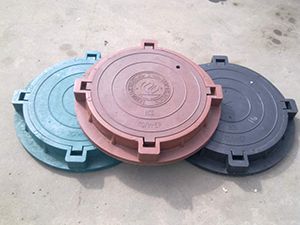
 | Polymer concrete hatch for drainage wells with a diameter of 340 mm. Country of origin: Russia. | 500 rub. | |
| Polymer concrete hatch for drainage wells with a diameter of 460 mm. Country of origin: Russia. | Designed for installation on drainage wells. Withstands loads of up to 1.5 tons. | 850 rub. | |
| Polyester geotextile with a density of 100 g/m². Country of origin: Russia. | Used to create drainage systems. Not susceptible to rotting, mold, rodents and insects. Roll length from 1 to 6 m. | 20 rub. for 1 m². |
From the presented table it can be seen that the cost of even Russian-made parts for drainage systems can hardly be called cheap. But the effect of their use will please the owners of the site for at least 50 years. This is the service life that the manufacturer claims. Considering that the material used to make drainage parts is absolutely inert with respect to all substances found in nature, we can assume that the service life will be much longer than stated.
Previously widely used asbestos cement or ceramic pipes We deliberately did not indicate them in the table, since apart from the high price and difficulties in transportation and installation, they will not bring anything. This is yesterday's century.

To create drainage systems, there are many more components from various manufacturers. These include tray parts, which can be throughput, connecting, prefabricated and dead-end. They are designed to connect drainage pipes of various diameters to wells. They provide drainage pipe connections at different angles.

Despite all the obvious advantages of tray parts with pipe sockets, their price is very high. For example, the part shown in the figure above costs 7 thousand rubles. Therefore, in most cases, the taps into the well indicated in the table are used. Another advantage of cut-ins is that they can be made at any level and at any angle to each other.
In addition to those parts for drainage systems that are indicated in the table, there are many others that are selected according to calculations and during installation on site. These may include various cuffs and O-rings, couplings, tees and crosses, check valves for drainage and sewer pipes, eccentric transitions and necks, bends, plugs and much more. Their correct selection should be done, first of all, during design, and then adjustments should be made during installation.
Video: How to choose a drainage pipe
Video: Drainage wells
If readers find articles on drainage on the Internet that say that it is easy to make drainage with your own hands, then we advise you to immediately close this article without reading it. Making drainage with your own hands is not an easy task. But the main thing is that this is possible if you do everything consistently and correctly.
Design of the site drainage system
The drainage system is a complex engineering object that requires appropriate treatment. Therefore, we recommend that our readers order site drainage design from professionals who will take into account absolutely everything: the topography of the site, existing (or planned) buildings, soil composition, groundwater depth, and other factors. After design, the customer will have a set of documents on hand, which includes:
- Plan of the site with its relief.
- A diagram for laying pipes for wall or ring drainage, indicating the cross-section and type of pipes, depth, required slopes, and location of wells.
- A drainage diagram of the site also indicating the depth of the trenches, types of pipes, slopes, distance between adjacent drains, location of rotary or water intake wells.

Do it yourself detailed project drainage system without knowledge and experience will be difficult. This is why you should turn to professionals
- A diagram of surface point and linear drainage indicating the size of trays, sand traps, storm water inlets, sewer pipes used, and the location of water intake wells.
- Transverse dimensions of trenches for wall and deep drainage, indicating the depth, material and thickness of the filling, and the type of geotextile used.
- Calculation of necessary components and materials.
- Explanatory note for the project, describing the entire drainage system and technology for performing the work.
The design of a site drainage system costs significantly less than an architectural design, so we once again strongly advise you to contact specialists. This minimizes the likelihood of errors when installing drainage yourself.
Home wall drainage equipment
To protect the foundations of houses from the effects of groundwater, so-called wall drainage is made, which is located around the entire house from the outside at some distance from the base of the foundation. usually it is 0.3-0.5 m, but in any case no more than 1 meter. Wall drainage is done at the stage of building a house along with measures for insulation and waterproofing of the foundation. When is this type of drainage necessary anyway?
- When the house has a ground floor.

- When the buried parts of the foundation are located no more than 0.5 meters above the groundwater level.
- When a house is built on clay or loamy soils.
All modern projects houses almost always provide wall drainage. The only exceptions can be those cases when the foundation is laid on sandy soils that do not freeze more than 80 cm.
A typical wall drainage design is shown in the figure.

At some distance from the base of the foundation, approximately 30 cm below its level, a leveling layer of sand of 10 cm is made, on which a geotextile membrane with a density of at least 150 g/m² is laid, on which is poured a layer of crushed stone of a fraction of 20-40 mm with a thickness of at least 10 cm. Instead of crushed stone, washed gravel can be used. It is better to use granite crushed stone, but not limestone, since the latter tends to be gradually eroded by water. A drainage pipe wrapped in geotextile is laid on a crushed stone bed. The pipes are given the required slope - at least 2 cm per 1 linear meter of pipe.
Inspection and inspection wells must be made at the places where the pipe turns. The rules allow them to be done every other turn, but practice suggests that it is better not to skimp on this and to place them at every turn. The slope of the pipes is made in one direction (in the figure from point K1, through points K2 and K3, to point K4). In this case, it is necessary to take into account the terrain. It is assumed that point K1 is at the highest point, and K4 at the lowest.
Drains are inserted into wells not from the very base, but with an indentation of at least 20 cm from the bottom. Then the small debris or silt that gets in will not linger in the pipes, but will settle in the well. Later, when inspecting the system, you can wash away the silty bottom with a strong stream of water, which will carry away everything unnecessary. If the soil in the area where the wells are located has good absorption capacity, then the bottom is not made. In all other cases, it is better to equip wells with a bottom.
A layer of crushed stone or washed gravel with a thickness of at least 20 cm is again poured over the drains, and then it is wrapped with a previously laid geotextile membrane. On top of such a “wrapped” structure from a drainage pipe and crushed stone, a backfill of sand is made, and on top, after compacting it, a blind area of the building is already organized, which is also intended to be used, but in a system of surface linear drainage. Even if atmospheric water enters from the outside of the foundation, after passing through the sand, it will enter the drains and through them will eventually flow into the main collector well, which can be equipped with a pump. If the terrain of the site allows, then an overflow without a pump is made from the collector well, removing water beyond the boundaries into a drainage ditch, an artificial or natural reservoir or a storm sewer system. Under no circumstances should drainage be connected to a regular sewer system.

If groundwater begins to “back up” from below, then it first of all saturates the sand preparation and crushed stone in which the drains are located. The speed of water movement through the drains is higher than in the ground, so the water is quickly removed and drained into a collector well, which is laid lower than the drains. It turns out that inside a closed loop of drainage pipes, water simply cannot rise above the level of the drains, which means both the base of the foundation and the floor in the basement will be dry.
This wall drainage scheme is very often used and works very effectively. But it has a significant drawback. This is backfilling the entire cavity between the foundation and the edge of the pit with sand. Considering the considerable volume of the sinus, you will have to pay a tidy sum for this filling. But there is a beautiful way out of this situation. To avoid backfilling with sand, you can use a special profiled geomembrane, which is a canvas made of HDPE or LDPE with various additives, having a relief surface in the form of small truncated cones. When the underground part of the foundation is covered with such a membrane, it performs two main functions.
- The geomembrane itself is an excellent waterproofer. It prevents moisture from penetrating the walls of the underground foundation structure.
- The textured surface of the membrane ensures that the water that appears on it flows freely downwards, where it will be “caught” by the installed drains.
The design of wall drainage using a geomembrane is shown in the following figure.

On external wall of the foundation, after installation and insulation measures (if necessary), the geomembrane is glued or mechanically fastened with the relief part (pimples) outward. A geotextile fabric with a density of 150-200 g/m² is fixed on top of it, which will prevent clogging of the relief part of the geomembrane with soil particles. Further organization of drainage proceeds as usual: a drain lined with crushed stone and wrapped in geotextile is placed on a layer of sand. Only the sinuses are filled not with sand or crushed stone, but with ordinary soil taken out when digging a pit or with clay, which is significantly cheaper.
The drainage of water “propping up” the foundation from below proceeds as in the previous case. But water that enters the wall from the outside through moistened soil or penetrates into the gap between the foundation and the soil will follow the path of least resistance: seep through geotextiles, flow freely along the relief surface of the geomembrane, pass through crushed stone and end up in the drain. Foundations protected in this way will not be threatened for at least 30-50 years. IN ground floors such houses will always be dry.
Let's consider the main stages of creating a wall drainage system for a house.
| Image | Description of actions |
|---|---|
 | After the construction of the foundation, its initial coating, and then roll waterproofing and insulation, a geomembrane is glued onto the outer wall of the foundation, including its base, with the help of a special mastic that does not corrode polystyrene foam, with the relief part facing outward. The upper part of the membrane should protrude beyond the level of the future backfill by at least 20 cm, and the lower part should reach the very bottom of the foundation, including the base. |
 | The joints of most geomembranes have a special lock that is “locked” by overlapping one sheet over the other and then tapping it with a rubber mallet. |
 | A geotextile fabric with a density of 150-200 g/m² is attached on top of the geomembrane. It is better to use thermally bonded geotextiles rather than needle-punched ones, since they are less susceptible to clogging. Disc-shaped dowels are used for fixation. The dowel fastening spacing is no more than 1 m horizontally and no more than 2 m vertically. The overlap of adjacent geotextile sheets on each other is at least 10-15 cm. Disc-shaped dowels should be located at the joint. |
 | In the upper part of the geomembrane and geotextile, it is recommended to use a special mounting strip, which will press both layers to the foundation structure. |
 | The bottom of the pit from the outside of the foundation is cleaned to the required level. The level can be controlled by a theodolite with a measuring bar, a laser level and a handy wooden bar with marked marks, tensioned and adjusted using a hydraulic level with a tensioned cord. You can also “beat off” a horizontal line on the wall and measure the depth using a tape measure. |
 | Washed sand is poured onto the bottom in a layer of at least 10 cm, which is moistened with water and compacted mechanically or manually until there are practically no traces left when walking. |
 | Inspection wells are installed in the designated locations. To do this, it is enough to use shafts with a diameter of 340 or 460 mm. Having measured the required length, they can be cut with a regular hacksaw, or a jigsaw, or a reciprocating saw. Initially, the wells must be cut 20-30 cm longer than the estimated length, and later, when designing the landscape, they must be adjusted to fit it. |
 | Bottoms are installed on wells. To do this, in single-layer wells (for example, Wavin), a rubber cuff is placed in the edge of the body, then it is lubricated with a soap solution and the bottom is installed. It should go in with force. |
 | In Russian-made two-layer wells, before installing the cuff, it is necessary to cut out a strip of the inner layer with a knife, and then do the same as in the previous case. |
 | The wells are installed in their intended places. The areas for their installation are compacted and leveled. On their side surfaces, marks are made for the entrance and exit of the drain centers (taking into account slopes of 2 cm per 1 linear meter of pipe). We remind you that the inlets and outlets of the drains must be at least 20 cm from the bottom. |
 | To make it easier to insert couplings, it is better to place the wells horizontally and make holes using a crown and a centering drill corresponding to the coupling. If you don't have a crown, you can make holes with a jigsaw, but this requires certain skills. |
 | After this, the edges are cleared of burrs with a knife or brush. |
 | The outer rubber sleeve of the coupling is placed inside the hole. It should go inside the well and stay outside equally (about 2 cm each). |
 | The inner surface of the rubber cuff of the coupling is lubricated with a soap solution, and then the plastic part is inserted until it stops. The junction of the rubber part of the coupling to the well can be coated with waterproof sealant. |
 | The wells are installed in their places and aligned vertically. Geotextiles are spread on a sand bed. Granite crushed stone of a fraction of 5-20 mm or washed gravel is poured onto it in a layer of at least 10 cm. The required slopes of the drainage pipes are taken into account. The crushed stone is leveled and compacted. |
 | Perforated drainage pipes of the required size are measured and cut. The pipes are inserted into couplings cut into the wells after lubricating the cuff with soapy water. Their bias is checked. |
 | A layer of crushed stone or gravel of at least 20 cm is poured on top of the drains. Then the edges of the geotextile fabric are wrapped on top of each other and sprinkled with a 20 cm layer of sand on top. |
 | In the designated location, a pit is dug for the collector well of the drainage system. Its level, naturally, must be below the lowest drain in order to receive water from the wall drainage. A trench is dug to this pit from the lower level inspection and inspection well for laying a sewer pipe. |
 | Shafts with diameters of 460, 695 and even 930 mm can be used as a collector well. A prefabricated well made of reinforced concrete rings can also be installed. Inserting a sewer pipe into a receiving collector well is done in exactly the same way as drains. |
 | The sewer pipe leading from the lower level of the wall drainage well to the collector well is laid on a 10 cm sand cushion and sprinkled with sand of at least 10 cm thickness on top. After compacting the sand, the trench is filled with soil. |
 | The system is checked for functionality. To do this, water is poured into the highest level well. After filling the bottom, water should begin to flow through the drains into other wells and, after filling their bottoms, eventually flow into the collector well. There should be no reverse current. |
 | After checking the functionality, the sinuses between the edge of the pit are filled with soil. It is preferable to use quarry clay for this, which will create a waterproof castle around the foundation. |
 | The wells are covered with lids to prevent clogging. Final trimming and installation of covers should be done in conjunction with landscaping work. |
A collector drainage well can be equipped check valve, which, even if it overflows, does not allow water to flow back into the drains. And also in the well there can be an automatic one. When the groundwater level increases to critical values, water will collect in the well. The pump is configured so that when a certain level in the well is exceeded, it will turn on and pump water outside the site or into other containers or reservoirs. Thus, the groundwater level in the foundation area will always be lower than the laid drains.
It happens that one collector well is used for wall and surface drainage systems. Experts do not recommend doing this, since during intense snow melting or heavy rains, a very large amount of water will accumulate in a short time, which will only interfere with inspecting the water drainage system in the area of the foundation. It is better to collect water from precipitation and melted snow in separate containers and use it for irrigation. In case of overflow storm wells water from them can be pumped in the same way to another place using a drainage pump.

Video: Wall drainage at home
House ring drainage equipment
Ring drainage, unlike wall drainage, is not located close to the foundation structure, but at some distance from it: from 2 to 10 meters or more meters. In what cases is ring drainage suitable?
- If the house has already been built and any intervention in the foundation structure is undesirable.
- If the house does not have a basement.
- If a house or group of buildings is built on sandy or sandy loam soils, which have good permeability to water.
- If other types of drainage fail to cope with the seasonal rise of groundwater.
Regardless of the fact that ring drainage is much simpler in practical implementation, the attitude towards it should be more serious than towards wall drainage. Why?
- A very important characteristic is the depth of the drains. In any case, the depth of the foundation must be greater than the depth of the base of the foundation or the level of the basement floor.
- The distance from the foundation to the drain is also an important characteristic. The sandier the soil, the greater the distance should be. And vice versa - the more clayey the soil, the closer the drains can be located to the foundation.
- When calculating the ring foundation, the groundwater level, its seasonal fluctuations and the direction of its inflow are also taken into account.
Based on all of the above, we can safely say that it is better to entrust the calculation of ring drainage to specialists. It would seem that the closer the drain is to the house and the deeper it is laid, the better it will be for the structure being protected. It turns out not! Any drainage changes the hydrogeological situation in the area of the foundation, which is not always good. The task of drainage is not to completely dry the area, but to lower the groundwater level to such values that will not interfere with human and plant life. Drainage is a kind of agreement with the forces of Mother Nature, and not an attempt to “rewrite” existing laws.
One of the options for constructing a ring drainage system is shown in the figure.

It can be seen that around the house, already outside the blind area, a trench has been dug to such a depth that the upper part of the drainage pipe lies 30-50 cm below the bottom point of the foundation. The trench is lined with geotextile and the pipe itself is also encased in it. The minimum underlying layer of crushed stone must be at least 10 cm. Minimum slope drains with a diameter of 110-200 mm - 2 cm per 1 linear meter of pipe. The picture shows that the entire trench is filled with rubble. This is completely acceptable and does not contradict anything other than common sense, in terms of unnecessary spending.
The diagram shows that the inspection and control wells are placed through one turn, which is quite acceptable if the drainage pipe is laid in one piece, without any fittings. But it’s still better to do them at every turn. This will make servicing the drainage system much easier over time.
A ring drainage system can “get along” perfectly with a surface point and linear drainage system. In one trench drains can be laid at the lower level, and next to them or on top in a layer of sand sewer pipes can be laid leading from trays and storm water inlets to a well for collecting rain and melt water. If the path of both leads to the same collector drainage well, then this is generally wonderful; the amount of excavation work is reduced significantly. Although, let us remind you that we recommended collecting these waters separately. They can be collected together only in one case - if all the water from precipitation and extracted from the ground is removed (naturally or forcibly) from the site into a collective storm sewer system, drainage ditch or reservoir.

When organizing ring drainage, a trench is first dug to the calculated depth. The width of the trench in the area of its bottom must be at least 40 cm; the bottom of the trench is immediately given a certain slope, the control of which is most convenient with a theodolite, and in its absence, a cord stretched horizontally and a measuring rod from available means will help.
Washed sand is poured onto the bottom in a layer of at least 10 cm, which is carefully compacted. Obviously, it is impossible to do this in a narrow trench using a mechanized method, so a manual tamper is used.
Installing wells, inserting couplings, adding crushed granite or gravel, laying and connecting drains is done in exactly the same way as when organizing wall drainage, so there is no point in repeating it. The difference is that with ring drainage, it is better to fill the trench after crushed stone and geotextiles not with soil, but with sand. Only the top fertile soil layer of approximately 10-15 cm is poured. Then, when landscaping the site, the places where drains are laid are taken into account and trees or shrubs with a strong root system are not planted in these places.
Video: Drainage around the house
Surface point and linear drainage equipment
As in all cases, a surface drainage system can only be successfully installed if there is a project or at least a self-made plan. On this plan, it is necessary to take into account everything - from water intake points to the container where rain and melt water will be drained. In this case, it is necessary to take into account the slopes of pipelines and trays, the direction of movement along the trays.

A surface drainage system can be installed on an existing blind area, paths made of paving slabs or paving stones. It is possible that some of their parts will have to be interfered with, but this still will not require complete dismantling. Let's consider an example of installing a surface drainage system using the example of polymer concrete trays and sand traps (sand traps) and sewer pipes.
To carry out the work you will need a very simple set of tools:
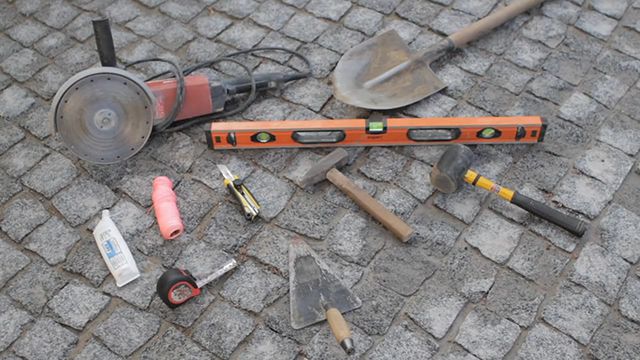
- Scoop and bayonet shovels;
- Construction bubble level from 60 cm long;
- Bench hammer;
- Rubber hammer for laying tiles or paving stones;
- Construction marking cord and a set of wooden stakes or pieces of reinforcement;
- Trowel and spatulas;
- Roulette;
- Construction knife;
- Chisel;
- Angle grinder (grinder) with discs of at least 230 mm for stone and metal;
- Container for preparing solutions.
We present the further process in the form of a table.
| Image | Process description |
|---|---|
 | Considering the surface drainage plan or project, it is necessary to determine the water discharge points, that is, those places where water collected from the surface will go into the sewer pipeline leading to the drainage well. The laying depth of this pipeline must be lower than the freezing depth of the soil, which for most populated climatic zones of Russia is 60-80 cm. It is in our interests to minimize the number of discharge points, but ensure the necessary throughput drainage |
 | Discharge of water into the pipeline must be done either through sand traps or through storm water inlets to ensure filtering of debris and sand. First of all, it is necessary to provide for their connection using standard shaped elements of external sewerage to the pipeline and try on these elements at the installation site. |
 | It is better to provide for the connection of rainwater inlets located under drainpipes in advance, even at the stage of arranging wall drainage, so that when the snow melts during thaws and the off-season, the water flowing from the roofs immediately enters the underground pipeline and does not freeze in the trays, blind areas and paths. |
 | If it is not possible to install sand traps, then you can connect the sewer pipeline directly to the trays. For this purpose, polymer concrete trays have special technological holes that allow connecting a vertical pipeline. |
 | Some manufacturers have special baskets attached to the vertical water discharge, which protect the drainage system from clogging. |
 | Most plastic trays, in addition to vertical connections, can also have lateral connections. But this should be done only when there is confidence in the purity of the discharged water, since it is much more difficult to clean drainage wells and catchment containers than baskets. |
 | To install surface drainage elements, you first need to select soil to the required depth and width. To do this, with an existing lawn, cut the turf to the required width, which is defined as the width of the element being installed plus 20 cm - 10 cm on each side. It may be necessary to dismantle curbs and outer rows of paving slabs or paving stones. |
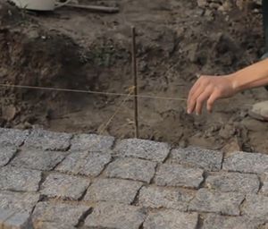 | In depth for installing drainage elements, it is necessary to select soil equal to the depth of the element plus 20 cm. Of these, 10 cm for sand or crushed stone preparation, and 10 cm for concrete base. The soil is removed, the base is cleaned and compacted, and then a backfill is made of crushed stone of a fraction of 5-20 mm. Then the pegs are driven in and the cord is pulled, which will determine the level of the trays to be installed. |
 | Elements of surface drainage are tried on at the installation site. In this case, the direction of water flow, which is usually indicated on the side surface of the trays, should be taken into account. |
 | Holes are made in the drainage elements for connecting sewer pipes. In plastic trays this is done with a knife, and in polymer concrete trays with a chisel and hammer. |
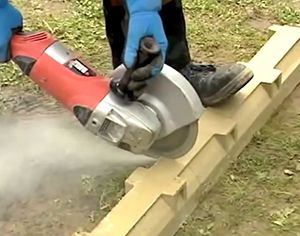 | When fitting parts, it may be necessary to cut off part of the tray. Plastic ones are easily cut with a hacksaw, and polymer concrete ones with a grinder. Galvanized metal grates are cut with metal shears, and cast iron grates are cut with a grinder. |
 | End caps are installed on the last trays using a special adhesive-sealant. |
 | To install surface drainage elements, it is best to use ready-made dry mixtures of sand concrete M-300, which are available from many manufacturers. A solution is prepared in a suitable container, which should be dense in consistency. It is better to install from the discharge points – sand traps. Concrete is laid on the prepared base. |
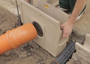 | Then it is leveled with a trowel and a sand trap is installed on this pad. |
 | Then it is aligned along the previously stretched cord. If necessary, press the tray into place using a rubber hammer. |
 | Check the correct installation using the cord and level. |
 | Trays and sand traps are positioned so that when the grate is installed, its plane is 3-5 mm below the surface level. Then the water will flow freely into the trays, and the grilles will not be damaged by car wheels. |
 | The leveled sand trap is immediately fixed on the sides concrete mixture. A so-called concrete heel is formed. |
 | Similarly, drainage trays are installed on the concrete base. |
 | They are also aligned both by cord and level. |
 | After installation, the joints are sealed with a special sealant, which is always offered when purchasing trays. |
 | Experienced installers can apply sealant before installing the trays, applying it to the ends before installation. |
 | When installing plastic trays into concrete, they may become deformed. Therefore, it is better to install them with installed grilles, which, to avoid contamination, are best wrapped in plastic film. |
 | If the surface is flat and has no slopes, then ensuring the required slope of the trays will be problematic. The way out of this situation is to install a cascade of trays of the same width but different depths. |
 | After installing all surface drainage elements, a concrete heel is formed, and then paving stones or paving slabs, if they were dismantled. The surface of the paving stones should be 3-5 mm higher than the grid of the drainage tray. |
 | Between the paving stones and the trays it is necessary to make expansion joint. Instead of the recommended rubber cords, you can use a strip of roofing felt folded in half and sealant. |
 | After the concrete has set, after 2-3 days you can backfill the excavated soil. |
 | After compacting the soil, the previously removed layer of turf is laid on top. It needs to be laid 5-7 cm higher than the rest of the lawn surface, as over time it will compact and settle. |
 | After flushing the entire surface drainage system and checking its performance, the trays, rainwater inlets and sand traps are closed with grates. It is possible to subject elements to vertical load only after 7-10 days. |
When operating a surface drainage system, it is necessary to periodically clean storm water inlets and sand traps. If necessary, you can remove the protective grilles and wash the trays themselves with a strong stream of water. Water collected after rains or melting snow is most suitable for later use for watering the garden, vegetable garden or lawns. Groundwater collected by a deep drainage system may have a different chemical composition and they cannot always be used for the same purposes. Therefore, we once again remind and advise our readers to collect groundwater and atmospheric water separately.
Video: Installation of a drainage system
Equipment for deep drainage of the site
We have already described in what cases deep drainage of a site is needed and found out that it is almost always needed in order to forever forget about the problems of stagnant puddles, constant dirt or the death of various plants that cannot tolerate waterlogged soils. The difficulty of equipping deep drainage is that if the site has already been landscaped, trees and shrubs have been planted, and there is a well-groomed lawn, then this order will have to be disrupted at least partially. Therefore, we recommend immediately organizing a deep drainage system on newly acquired plots for construction. As in all other cases, the design of such a drainage system must be ordered from specialists. Independent incorrect calculation and execution of the drainage system can lead to the fact that waterlogged areas on the site will be adjacent to dry ones.

In areas with pronounced topography, a drainage system can become a beautiful part of the landscape. To do this, an open canal or network of canals is organized through which water can freely flow beyond the site. Storm drains from the roof can also be directed into the same channels. But readers will certainly agree with the authors that the presence of a large number of channels will bring more inconvenience than benefits from their contemplation. That is why deep drainage is most often installed closed type. Opponents of deep drainage may argue that such systems can lead to excessive drainage of fertile soil, which will negatively affect plants. However, any fertile soils have very good and useful property- they retain exactly as much water in their thickness as is necessary, and plants growing on soils take from it exactly as much water as is necessary for their root system.

The main guiding document for organizing a drainage system is a graphic plan of the drainage system, which indicates everything: the location of collector and storage wells, the cross-section of drainage pipes and their depth, cross-section drainage trench and another helpful information. An example of a drainage system plan is shown in the figure.
Let's consider the main stages of creating deep drainage of the site.
| Image | Process description |
|---|---|
 | First of all, the site is marked, in which the position of the main elements of the drainage system is transferred from the plan to the terrain. The routes of the drainage pipes are marked with a tensioned cord, which can immediately be pulled either horizontally or with a slope, which should be in each of the sections. |
 | A pit is dug for a storage drainage well of the required depth. The bottom of the pit is compacted and 10 cm of sand is poured and compacted onto it. The body of the well is tried on in place. |
 | A trench is dug in the direction from the well towards the beginning of the main collector pipe, the bottom of which is immediately given the required slope specified in the project, but not less than 2 cm per 1 linear meter of pipe. The width of the trench near the bottom is 40 m. The depth depends on the specific project. |
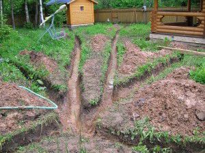 | From the collector trench, trenches are dug for drains that will be connected to the collector pipe. The bottom of the trenches is immediately given the required slope. The width of the trenches in the bottom area is 40 cm. The depth is according to the project. On clay and loamy soils, the average depth of drains is 0.6-0.8 meters, and on sandy soils - 0.8-1.2 meters. |
 | The locations of rotary and collector inspection manholes are being prepared. |
 | After checking the depth and required slopes, 10 cm of sand is poured onto the bottom of all trenches, which is subsequently wetted and compacted manually. |
 | Geotextiles are lined at the bottom of the trenches so that they extend onto the side walls. Depending on the depth of the trench and the width of the geotest fabric, it is fixed either on the walls of the trench or on top. |
 | The wells are installed and tried on in their places, the places where the couplings are inserted are marked. Then the wells are removed and the necessary couplings are cut into them to connect the drains, and the bottoms are mounted. |
 | The wells are installed in their places and leveled. A layer of granite crushed stone or washed gravel with a fraction of 20-40 mm and a thickness of 10 cm is poured into the trench. The crushed stone layer is compacted and the necessary slopes are created. |
 | The required sections of drainage pipes are cut off and equipped with plugs (if necessary). In most cases, beam drains are made from pipes with a diameter of 110 mm, and collector drains – 160 mm. The pipes are laid in trenches and connected to well couplings and fittings. Their depth and slopes are checked. |
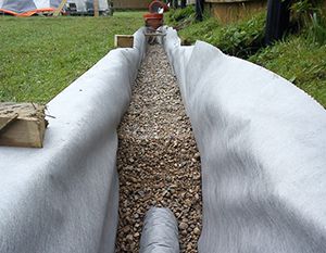 | A 20 cm layer of crushed stone or washed gravel is poured over the drains. After compaction, the crushed stone layer is covered with geotextiles previously fixed to the walls of the trenches or on top. |
 | The drainage system is checked for functionality. To do this, in various places where drains are laid, a large amount of water is poured into the trenches. Its absorption into the crushed stone layer and flow through rotary, collector wells and into the main drainage well are controlled. |
 | A layer of sand is poured over the geotextile, at least 20 cm thick. The sand is compacted, and on top of it the trenches are filled with fertile soil - 15-20 cm. |
 | Covers are put on the wells. |
Even if deep drainage of the site was done without a project, it is still necessary to draw up a plan to indicate the location of the drains and their depth. This will help in the future, when carrying out any excavation work, to leave the system undamaged. If the terrain allows, then drainage wells may not be installed, and the water collected by drains is immediately sent to sewers, reservoirs or a collective storm sewer system. Any of these steps must be coordinated with neighbors and village administrations. But a well is still desirable, at least to control the groundwater level and its seasonal fluctuations.
A collector well for collecting groundwater can be made overflow. When the water level in such wells becomes higher than the overflow pipe, some of the water flows through the sewer pipe into another storage well. This system allows you to get clean water in the storage well, since all the dirt, silt and debris settles in the collector overflow well.
When famous thinkers, called great, whose sayings are constantly quoted and cited as examples, put their thoughts on paper, they probably did not even suspect that they were writing about deep drainage. Here are some examples:
- A collective image of a thinker who is known to most people, like Kozma Prutkov, said: “Look at the root!” Great phrase about deep drainage! If the owner wishes to grow on his plot garden trees, then you simply must know where the groundwater lies, since its excess in the area of the root system has a bad effect on most plants.
- The very famous thinker and “wisdom generator” Oscar Wilde also said, without knowing it, about deep drainage: “The biggest vice in a person is superficiality. Everything that happens in our lives has its own deep meaning.”
- Stanislaw Jerzy Lec said the following about depth: “A swamp sometimes gives the impression of depth.” This phrase fits drainage perfectly, since without it the area may well turn into a swamp.
We can give many more quotes from great people and connect them with drainage, but we will not distract the readers of our portal from the main idea. For the safety of homes and the comfort of their inhabitants, creating ideal conditions for the growth of necessary plants, and arranging a cozy landscape, drainage is definitely needed.
Conclusion
It should be noted that residents of most regions of Russia are incredibly lucky if the issue of drainage is raised. An abundance of water, especially fresh water, is much better than a lack of it. Residents of arid and desert regions, having read such an article, would sigh and say: “We would like your problems!” Therefore, we simply must consider ourselves lucky that we live in a country that does not lack fresh water.
As we have already noted, you can always “negotiate” with water using the drainage system. The modern market abundance offers a simply gigantic assortment of various components, allowing you to create a system of any complexity. But in this matter one must be very selective and careful, since excessive complexity of any system reduces its reliability. Therefore, we again and again recommend ordering a drainage project from specialists. And the independent implementation of site drainage is within the capabilities of any good owner, and we hope that our article will help in some way.