The wafer check valve belongs to the shut-off pipeline valves. Compared to conventional shut-off valves, the part is small in size, has a simple operating mechanism and can be easily installed.
The wafer check valve works equally effectively on both horizontal and vertical sections of the pipeline. These shut-off valves are used both in household communications and in production, when transporting aggressive, dangerous liquids and gases on an industrial scale.
The fittings are designed to block the possibility of changing the direction of liquid or gas in a pipe during a drop in pressure, emergency situations, or as a result of water hammer. In household communications, these shut-off devices are used in ventilation systems, heating communications, and when installing sewage drains.
Preventing backflows in pipeline services is critical to the efficient and safe transport of liquids or gases.
The formation of reverse flow is fraught with failure of pipelines and the creation of emergency situations with serious consequences.

The most harmless example that can be given is the formation of a backflow in a sewer pipe, when the discharged waste suddenly rushes back and begins to flow from all technological openings for its discharge.
Wafer check valves are installed without threads, using rubber gaskets as an insulating seal.
- Wafer check valve is used:
- To prevent the possibility of a change in flow direction as a result of a pressure difference in the pipe, for example, when turning off the forced transport pump.
To equalize the flow force. Here, shut-off valves of this type play the role of a control gateway during water hammer, preventing emergency situations.
Note! The wafer check valve operates automatically and does not require additional maintenance after installation.
Operating principle
Protective pipeline fittings are found everywhere in our lives. In any house, at any factory, gas station, oil well, farm, boiler room, and even at the water supply to the apartment, check valves are used everywhere to protect the system and equipment from the reverse flow of water, gas, fuel and many other fluids.
We welcome our reader and bring to his attention an article about the types of protective fittings for pipelines.
Wafer check valve – protects networks and equipment.
A check valve is a protective pipeline fitting that allows the flow of a medium to flow in one direction and blocks the movement of a medium in the opposite direction. It is a direct-acting valve and is activated automatically by the return movement of the working medium.
By design, check valves are divided into:
- for ball or receivers;
- check valves;
- wafer;
- combined (combined with shut-off valves).
Wafer products are characterized by compact dimensions and installation method - in flanged pipeline breaks.
Purpose and scope of application
With the help of check valves, pipeline systems, equipment, pumps, heating boilers, and automation are protected from water hammer; if a seal is broken or part of the system is destroyed, they reduce leakage.
In technological schemes, check valves are used:
- in closed systems for make-up;
- after installing meters and other control and measuring equipment;
- in systems with several pumps;
- in heating systems on the jumper between the supply and return pipelines;
- in all kinds of supply pipelines where the movement of the medium in one direction is required;
- in ventilation systems;
- in filter systems, treatment facilities - to ensure the movement of liquid through the filter or only in one direction;
- in everyday life - in wells together with a deep submersible pump, in quick-release couplings of irrigation systems, in thermostatic fittings for heating systems in private homes.
The areas of application of protective fittings are in all areas of industry, mining, everyday life, agriculture, transport, and the gas transmission system.
Check valves are used in systems with both liquid and gaseous media.
Controls and technical characteristics
Connection type
Wafer check valves can be installed in pipelines in both vertical and horizontal positions.
The design feature of connecting such valves is that they do not have flanges for installation in the pipeline - they are clamped between the pipeline flanges.
Device
Wafer designs are characterized by the absence of flanges. In their body there is a working element - a disk, flaps, which, when the flow of the medium changes to reverse, block the passage and prevent the reverse flow of gases and liquids.
Note! The wafer check valve operates automatically and does not require additional maintenance after installation.
The principle of operation of check valves is based on the fact that in the absence of medium flow, the working body (disk, spool, ball) under the influence of its own weight and additional devices moves to the “closed” position (sits in the housing seat).

When a flow occurs, the valve under its pressure moves to the “open” position and opens the passage through the seat. If the flow of liquid or gas changes position to the opposite, it stops, the valve moves to the closed position, then the pressure of the liquid or gas additionally presses the spool, ball or disk - the passage is securely blocked.
The check valve is activated automatically under the influence of the moved medium, without additional control or regulation.
Types and designs
Structurally, wafer check valves are either double-leaf or spring disc.
Spring-operated disc models (sometimes called single-leaf) have a shutter in the form of a flat disc, which, in the closed position, is pressed against the body seat by a spring.

The thin disk takes up little space in the case, which greatly reduces the weight and overall length of the mechanism. The use of a spring and the light weight of the disk make it possible to install the fittings in both vertical and horizontal positions.
Such models are installed on pipelines with a working diameter of 15-200 mm.

Double-leaf models are more reliable than disk models and are used in more complex and larger systems with working diameters from 50 to 700 mm.
In a double-leaf check valve, the gate elements are two flaps (segments or petals) mounted on an axis. The axis runs through the center of the passage, and springs are attached to it.

In large hydraulic or pneumatic systems, dangerous water hammer often occurs (during emergency situations, pump shutdowns, etc.). In such cases, valves with shock absorbers are used to dampen sudden pressure surges in the hydraulic system.

Check valves, based on the material from which they are made, are:
- made of structural alloy steel;
- stainless steel;
- made of brass and bronze;
- made of cast iron;
- made of titanium;
- made of aluminum;
- made of bronze;
- combined.
In the marking, in second place are the letters that indicate the material.
Differences between a flanged valve and a wafer valve
Flange models differ from wafer models:
- construction length - for flanged models it can be 6-8 times longer than for wafer models;
- the weight of flanged models can be 5 times greater;
- by installation method: flanged ones are mounted in the pipeline using flanges;
- wafer type are clamped between the pipeline flanges.
Advantages and disadvantages
Advantages:
- small dimensions, including construction length;
- light weight;
- affordable price;
- possibility of installation on both vertical and horizontal sections of the pipeline;
- simple design;
- reliability;
- does not require maintenance;
- good maintainability.
A significant disadvantage of wafer-type products is a significant loss of pressure on the valve (since there is a working element in the passage - a valve with an axis, a disk). When installing in large hydraulic systems, it is necessary to take into account the pressure loss in the calculations of system parameters. Disc models inhibit the flow of the medium more strongly than sash models. Disc models do not work well in conditions where the liquid contains impurities, such as sand.
Please note that check valves do not replace conventional shut-off valves and gate valves.
In almost everyday life, we may encounter the installation of a coupling check valve (clutch valve) after the water meter and at the inlet of the heating system. Choosing a shutter for a meter makes virtually no sense - they are sold everywhere and produced in every region. The technology and design are also the same everywhere. Material: brass. The main thing is to buy it in a store, with a receipt, a guarantee, and inspect it visually. The most important thing is that the nominal diameter coincides with the diameter of the water meter!
Work on the heating system input must be carried out by utility specialists. But it is likely that under certain conditions the residents of the house will still have to buy and select components for the input unit. The most important thing is to purchase from a construction hypermarket, with a guarantee, the required nominal diameter. The choice of materials is very important: the ideal, but expensive option is stainless steel or brass.
The best option in terms of price/quality ratio - structural steel with a stainless steel working body - also works well and lasts a long time.
Rules for installation and operation of the device
Required tools and materials
For the water meter you need: the valve itself, gaskets of the required diameter (preferably made of silicone), two adjustable wrenches, FUM tape.
Connection diagram
The valve is installed immediately behind the meter.

When installing, you must ensure that the direction of water flow coincides with the arrow on the device body.
Work progress
Installation procedure:
- the water meter pipe with the union nut is disconnected from the water meter;
- the threads of the pipe of the intra-apartment or intra-house network and the water meter pipe are carefully wrapped with FUM tape;
- screw the pipe into the valve;
- screw the valve onto the thread of the internal network, the arrow of the direction of water flow should be directed away from the meter;
- a gasket is installed in the union nut;
- screw the nut onto the connecting pipe of the meter;
- Let the water flow and test the connection; if there is a leak, tighten the connections.
We suggest watching the video for installing a check valve on a water meter:
Frequent errors and problems during installation
In practice, there can be only one mistake: installation is not in the direction of water movement. And there may still be leaks.
When installing the valve in the opposite direction, water will not flow into the meter and the apartment - you will have to unscrew it and reinstall it. In case of leaks, tighten the connections.
When installing a water metering unit, especially in a steel water supply system, it may be inconvenient to install - there will not be enough space to screw on the union nut at the last moment. In this case, it is worth supplementing the metering unit with another union nut - an “American” one on the valve side (of the “nut-fitting” type).
A wafer check valve will help reduce damage from accidents in the water supply system, contain water hammer, and stabilize the pressure. This shut-off element in the pipeline performs the following functions:
- does not allow the fluid flow to reverse direction. Such a danger arises due to a drop in pressure, its changes;
- equalizes the flow pressure in the event of water hammer or emergency situations.
They install shut-off devices in water supply, heating mains, and sewer drains.
Advantages of locking modules
Wafer check valves are popular among consumers due to the following advantages:
- suitable for installation at any point on the highway;
- can serve both horizontal and vertical pipelines;
- have small dimensions, extending the pipelines only slightly;
- they cost little.
Specifics of the hazards that the wafer check valve protects against
The flow of fluid in technical lines can change its direction due to various reasons. For example, in the pipes of a heating system, the heat-carrying liquid must flow continuously, which is ensured by the operation of special pumps. Pumps apply pressure to the stream to keep it moving. If a malfunction occurs in one of the pumps and it stops, a vortex-type funnel will form in the pipe, and the pressure difference will provoke a flow reversal in the opposite direction.
Water hammer is a shock wave caused by a sudden change in pressure in the pipeline. Such a wave has sufficient strength and travels along the entire length of the pipe. Strong areas will resist, but worn areas may be seriously damaged.
Water hammers in water mains occur with a certain frequency, which is why locking wafer mechanisms are installed in them, which protect pipes from premature wear and accidents. Locks on both sides isolate the section of the pipe where the pressure drop occurs and prevent the shock wave from spreading along the line and damaging it.
Functionality, technical parameters, basic information
The locking device operates on a simple principle. The valve, installed in the direction of flow, allows liquid to pass through. This occurs when sufficient force presses on the valve flaps, thereby opening them. If the pressure decreases, the valves close, hermetically blocking the channel.
Wafer valves differ from standard check valves in the absence of counter flanges in the design, which must connect the valve to the pipe. Installation of the mechanism into the pipe is carried out by simply clamping it between its flanges. Because of this feature, the design is compact, has reduced dimensions, five times less weight, and eight times less construction length compared to valves of other designs. All this significantly reduces purchasing and installation costs.
The dimensions of the valves and the material of the gaskets must correspond to the flow of the working fluid and its properties. Most often, sealing surfaces are made of rubber, brass, and bronze. They can be overlaid with steel or an alloy that is resistant to corrosion. It is these gaskets that ensure the tightness of the locking element. Wafer check valves are installed without using a threaded connection, and the seal is insulating rubber gaskets.
Paronite can serve as a sealing material. It is made from several components (rubber, asbestos powder, powder fillers), the mixture of which is vulcanized to a flat sheet, then rolled. Paronite gaskets are capable of sealing even aggressive high-temperature liquids under strong pressure (water heated to temperatures above 100 degrees, liquids containing alkalis, salts, acids, etc.).
Device cases are made of cast iron, brass, alloys, and less commonly, stainless or ordinary steel. Cast iron mechanisms with stainless steel valves are universal and suitable for use in highways for various purposes.
The double-leaf wafer check valve, depending on the model, can have a diameter of 50-700 mm. The greatest demand is for a 150 mm wafer water check valve.
The lining (internal lining) of shut-off devices can be:
- anti-corrosion;
- rubber (for technical fluids);
- plastic (for drinking water).
A wafer spring check valve has a spring as a pressing element, and a plate (disc) performs the function of a shutter. This allows the valve to be lighter and have a short face-to-face length. Such devices are usually used for highways of small diameters (15-200 mm). Spring models often have special threaded holes that remove static electricity, which is especially important for the production of chemical explosives.
Typically, shut-off valves can withstand the temperature of the working medium (water) up to 120-225 degrees Celsius. Products with a rubber seal can withstand not too high temperatures.
Double flange check valve: types, features
Based on the number of valves, a distinction is made between a single-leaf wafer check valve and a double-leaf check valve. Devices with two dampers can be equipped with a spring, which is optimal for installing pipes with a diameter of 5-8 cm.
There are different locking modules based on the type of locking mechanism.
- Lifting. Its design is simple: the flow of liquid lifts the spool vertically along its axis, when the force of the flow weakens, the valve falls onto the hole under the influence of its weight, blocking it.
- Spring-type: a spring presses on the valve; if the opposing pressure of the jet is insufficient to resist its force, the flow is blocked.
- Wafer disc check valve. Typically made from galvanized steel. Suitable for servicing pipes with water of any temperature (up to 130 degrees and above) under pressure up to 1.6 MPa.
- Wafer type rotary check valve (impact, non-impact). It acts like a spool device and is equipped with a filter (mesh). The flow is controlled by a sash that closes on a spring. Indispensable for communications of large diameters (up to 15 cm), pipelines transporting liquid contaminated with impurities. Most often it is used for flows with high temperatures (heating communications, water supply branches supplying hot water). Their most popular diameter is 5-11 cm.
Installation of valves in the pipeline: features, description of the process
When installing the valve, additional components will be required:
- paronite, rubber gaskets (both sizes DN-40, 50, 80, 100, 150, 200);
- bolt M16*70, 20*90;
- nut, washer, stud, all sizes M16, 20.
Before installation, it is useful to treat paronite seals with graphite powder to prevent them from sintering with pipeline elements.
Installation procedure
First of all, the technical characteristics of the locking element and its documentation are carefully studied. An external inspection is carried out to identify damage, if any. Valves with defects are not suitable for installation in pipelines. Operating parameters during operation must correspond to those specified in the accompanying instructions.
Product marking
Check valve models are identified by two abbreviations that tell the user their main characteristics.
The article "RU" encodes the operating pressure at which the valve can operate. Most often this figure is 16 atmospheres.
The parameter “DN” (or “DN”) denotes the nominal diameter, that is, the internal diameter of the part in millimeters, usually ranging from 40-600 mm.
Installation
The valve is installed based on several principles.
- The installation location is determined in advance. It is desirable that access to the selected point be free. If the lock needs to be installed in the area of a pipe bend, it is mounted in the direction of flow on a straight section, slightly away from the bend, and not immediately after it. This is explained by the fact that in the inner area of the “elbow” the fluid flow is the smallest; its force may not be enough to open the damper; some distance is required to stabilize the flow.
- The diameters of the locking mechanism and pipe must match.
- When assembling the system, the locking device is mounted sequentially. When it is installed in an already existing system, part of the pipe is cut out and a valve is fixed in this place.
- In horizontal pipes, the valves are mounted so that the axis of the valves is horizontal, in vertical pipes - with the inlet hole down.
- Collar flanges are attached to the pipe, and a locking mechanism is inserted between them. The distance between the flanges must exactly match the dimensions of the valve in order for the connection to be airtight.
- Upon completion of installation, the operation of the system is checked. Before putting the pipe line into operation, it is useful to blow it out to remove mechanical debris.
During installation, the shutter mechanism is oriented in the direction of flow; for this purpose, there is a special indicator on the lock in the form of an arrow or hook.
After installation, the locking module functions independently and does not require any maintenance.
How to choose and buy locking elements
In order to correctly select wafer check valves for the parameters of a particular pipeline, the following aspects are clarified:
- type of working environment, its temperature, pressure;
- optimal design of the locking mechanism;
- dimensions, valve material.
All these indicators affect the final cost of the products.
The Teharmatura company presents for sale wafer valves of various diameters. The products are capable of working with working environments with temperatures from 120 to 225 degrees Celsius. The valves offered can serve different types of media: drinking water, technical water, hot water, cold water.
The quality and reliability of locking fittings is confirmed by their guarantee and quality certificates. The quality level of the valves is determined by a double check: water flow, air stream.
In any systems whose design includes a pipeline, it is provided that the working fluid is transported in one direction. In order not to encounter a change in the direction of its movement, which can lead to failure of the entire system, various technical devices are used, one of which is a wafer check valve. It is equipped with pipelines used by oil refining and chemical industry enterprises, through which both liquid and gaseous working media are transported.
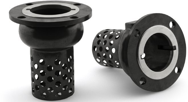
Wafer check valve - “flap” made of stainless steel for use in various aquatic environments
Design features and characteristics
A wafer valve, like all check valves, is used to block the flow of a gas or liquid if it begins to move in the wrong direction. In other words, it is a kind of locking device. Wafer check valves, unlike many others, can be installed in both horizontal and vertical positions. Depending on the features of their design, they can be:
- spring;
- pneumatic, made of stainless steel;
- double-leaf couplings made of cast iron;
- rotary type, made of stainless steel.

The installation process for wafer valves of all the above categories is the same and does not cause any particular difficulties.
Among the advantages that check valves of the wafer type have, it should be noted their compact dimensions, which makes it possible to use them in cramped conditions where it is not possible to use other valve products. Thanks to the use of such compact valves, it is possible to reduce the length and other parameters of the installed system, which is important in many situations.

There are several most common modifications of wafer check valves, each of which differs in certain technical characteristics. So, if we talk about models of such devices, among them we should highlight:
- 19С53Нж - devices that are easy to operate and maintain;
- 16Ch42R – wafer type check valves, which are made of especially durable materials;
- RU16 are models that are characterized by high reliability of the connection created with their help.

Main varieties
If we review the most popular check valve devices, we should start with rotary models, in particular with the DN150 wafer valve. DU150, like other models, allows the flow of the working medium through itself in only one direction. If the direction of movement of the working fluid flow changes, the valve is automatically blocked and its shutter is closed.
Among the check valves belonging to the class of rotary valves, there are:
- simple;
- unstressed.
The locking element of rotary-type check valves is a spool, which allows them to be used even when working with heavily contaminated working media. In addition, the design features of such valve devices make it possible to use them for pipelines of even significant diameter (from fifty to one hundred and fifty millimeters).

Rotary check valves, the structural elements of which are made of brass, are used to equip heating systems, as well as water and heat supply systems. The design of such valves, which operate primarily with a liquid working medium, includes a mesh that acts as a filter element.
Depending on their design, rotary check valves can be one of three types:
- coupling;
- flanged;
- wafer
Wafer devices, in turn, are divided into check valves of the following types:
- reverse wafer valve made of stainless steel;
- double-leaf type wafer check valve;
- check wafer valves made of cast iron.

Popular models of check valve wafer devices, for the manufacture of which steel alloys are used, are also DN25, 32, 50, 80, 110. The most significant advantages of these valve devices are compact dimensions and affordable cost. Meanwhile, when using wafer valves in a pipeline, a significant loss of pressure of the transported working medium occurs.
Among the many check valves offered by modern manufacturers, we should highlight the DU150 flange lift valve and the DU100 model, which are installed and successfully used on pipelines for various purposes. Mention should also be made of a brass wafer check valve with two flaps mounted on the same axis. Valve devices of this type, characterized by unpretentious installation, are used to equip pipelines whose diameter is in the range of 50–80 mm.
Based on the material of manufacture, flanged valve devices are divided into the following types of products:
- wafer-type steel check valve with protective mesh;
- cast iron check valve, also equipped with a mesh that acts as a filter element.
Valves made of cast iron or steel alloy are large in size and weight, which somewhat limits their scope of application.
In order not to significantly lose pressure in the working medium transported through the pipeline, it can be equipped with spring-type check valves, which can be made of either cast iron or brass alloy. Flanged check valves are also equipped with a spring, the most popular models of which include DN50, 80, 110. Their great advantage is that they can be installed in both horizontal and vertical positions. In addition, wafer spring check valves can successfully withstand such phenomena as water hammer.
Closing of the valve in check valves that are not equipped with a spring is ensured by the force of gravity that the valve itself has. Their installation can be carried out both horizontally and vertically, but only if the flow of the working medium transported through a vertical pipeline is directed from bottom to top.
Today, ventilation systems are also equipped with reverse air seals, which is necessary in order to prevent contaminated air from entering back into the ventilated room. Such devices can be found in ventilation systems serving not only industrial premises, but also office and domestic premises (kitchens, sanitary facilities, etc.). In addition, ventilation systems installed in public buildings – shopping and entertainment centers, shopping malls, etc. – are equipped with check valves.

The design of check valves installed in ventilation systems is formed by a rotating axis on which special blades are fixed. These blades can cut off the air flow due to a special spring or gravity.
Another type of such devices is a poppet (or disk) check valve, the closing element of which is a disk located in a seat with a sealing element. The shut-off element in the disc check valve is fixed on a rod that can move freely in the device body. The disc type check valve can be wafer or coupling. It is used to equip both pipelines through which gaseous working media are transported and ventilation systems.
Check valve modifications and manufacturers
Among the popular manufacturers of check valve devices are the following companies:
- Tecofi (France);
- FAF (Türkiye);
- FERRO (Poland);
- Westshintorg (Republic of Belarus).
If we talk about the most popular models, they are valves DN32, 50, 80, produced by the French company Tecofi. These models, which are made from stainless steel, are distinguished by their practicality, high reliability and long service life, which makes them so popular among domestic consumers.

The main parameters that influence the cost of reverse valve devices are:
- appointment;
- design;
- material of manufacture;
- valve dimensions and cross-section of its mounting holes.
A brief overview of the main technical characteristics of the most popular models of check valves will give an opportunity to get an idea of these devices.DN50
The body of the check valve of this model (16CH42R) is made of cast iron, and its shutter part is made of brass. Thanks to the manufacture of the DN50 valve part from stainless material, it can be used to equip pipelines through which water and steam are transported. The check valve of this model can operate at a temperature of the working medium exceeding 225° and at a pressure of 1.6 MPa.
Such a check valve is installed on both horizontal and vertical pipelines. At the same time, on vertical pipelines it is located with the inlet pipe down, and on horizontal pipelines the axis of rotation of its flaps should be in the horizontal plane.

The DU80 wafer type check valve, the body of which is made of galvanized steel or cast iron, and the sealing element is made of rubber, can be used for installation on pipelines through which hot and cold water is transported. The maximum temperature of the working medium that the DU80 can withstand is +90°, and the maximum pressure is 1.6 MPa.
DU100This disc type check valve has elements made of galvanized steel. DU100 can be used in pipelines through which cold and hot water and steam are transported; it can withstand a pressure of 1.6 MPa and a temperature of +130°.
DU150The body of the wafer check valve of this model, used to equip pipelines for various purposes, is made of cast iron, and the shut-off elements, which are two spring-loaded flaps, are made of stainless steel. DU150 is also used to equip pipelines through which petroleum products are transported, and can be installed in both horizontal and vertical positions. The operating pressure at which the check valve of this model can be operated is 1.6 MPa.