Once upon a time they gave me this Chinese lantern.


After six months of use, it stopped turning on. I open the case to determine the cause of the failure.

They forgot to turn off the flashlight after use. Due to the absence of any protection circuits, the lead batteries were discharged to zero. Apparently, sulfation of the plates occurred, and when charging the batteries practically did not consume current. Then the mains voltage from transformerless charging, through the switched on toggle switch, rushed to the LEDs. As a result, all 15 LEDs failed, and only the housing remained in working condition.
Having looked at the insides of this Chinese lantern, I will immediately note its main disadvantages:
- there is no protection against deep battery discharge (discharges to zero)
- there is no control over the battery charging process (charges endlessly)
- no low battery indication
- terrible retractable power plug design
I decided to repair the flashlight, making a complete upgrade and replacing all the internals. So, what would you like to get in the end:
- powered by lithium-ion battery (for lighter weight)
- battery charging through a specialized controller (with indication and automatic shutdown)
- turning the flashlight on/off using a tact button
- indication of fast battery discharge (voltage 3.7V)
- shutdown when the battery is completely discharged (voltage 3.6V)
- USB charging capability
- Automatic shutdown of the flashlight when charging
- design without the use of rare, expensive components and microcontrollers
No sooner said than done. Control unit diagram.

I will briefly describe the main components of the circuit:
- Components DA4, VT3, R17, R24, C16 form a secondary protection unit against battery discharge. This unit disconnects the load from the battery when the voltage drops to 2.5 Volts. The secondary protection unit does not need to be installed, but the installation of jumper R12 will be required.
- Components DA3, R16, R18, R21, HL2, HL3, C9, C13 form a battery charging unit with automatic shutdown, current control, and indication of the charging process.
- Components DD1, C11, R19, VD1 form the trigger necessary to control the flashlight using a tact button.
- Components C12, R20, R22 assemble a circuit for suppressing contact bounce of the SB1 button.
- Circuit R15, VD3 resets the trigger when the flashlight is charged.
- Components VT1, VT2, R13, R14 organize power supply to the circuit and LEDs.
- Components DA1, C1, C3, R5, R6, R7, C4, C5 form a 1.25 Volt reference voltage.
- Components DA2, HL1, C2, R2, R3, R4, R8 form a low battery charge indication unit.
- Components DA2, R9, R10, C8, VD2 form the primary protection unit against battery discharge.
- Resistors R1, R11, R23 act as fuses.
Let's move on to hardware. First, I'll start restoring the LED block. I unscrew the reflector.


I dismantle burnt out LEDs.

I solder working LEDs taken from an old faulty flashlight. I also change all resistors to 100 ohm.

The LED block has been restored. Block diagram.

Now I'll start making the control board. To do this, I take all the dimensions and print a makeshift board on a printer.

I lay out the printed circuit board, manufacture it using LUT technology, and solder the components.


On the left you can see that the secondary protection unit against battery discharge is not soldered to the board; instead, jumper R12 is installed.

Now you need to turn the switch into a tact button. I'm taking apart the switch.

I cover the standard cutout with a piece of black plastic.

I drill holes.

I attach a small scarf with a clock button.

The button is ready.

Initially, the flashlight was equipped with a single indicator that lit up when plugged into the network. In fact, this indicator was absolutely useless. The upgraded board contains three indicators - red, green, yellow.

It is necessary to drill holes in the plastic insert for the light guides.

I removed the light guides from an old CRT monitor.

Upgraded plastic insert with light guides.


I install the board with the battery into the flashlight body. The battery is attached to the board using double-sided tape.

Inside the case, the board feels like its own.

I put the plastic inserts back in place.

I'm assembling the body.

The flashlight has become reliable and convenient. Using it is a pleasure.

A red light means the battery is almost empty and the flashlight will turn off soon.

When charging, the yellow indicator lights up.

At the end of the charging process, the green indicator lights up.

Finally, I suggest you watch a short video.
List of radioelements
| Designation | Type | Denomination | Quantity | Note | Shop | My notepad |
|---|---|---|---|---|---|---|
| R1, R11, R23 | Resistor | 0 ohm | 3 | 1206 | To notepad | |
| R2 | Resistor | 10 kOhm | 1 | 0805 | To notepad | |
| R3 | Resistor | 1 MOhm | 1 | 0805 | To notepad | |
| R4 | Resistor | 5.1 kOhm | 1 | 0805 | To notepad | |
| R5, R18, R21 | Resistor | 300 Ohm | 3 | 0805 | To notepad | |
| R8 | Resistor | 300 Ohm | 1 | 1206 | To notepad | |
| R6, R7, R15 | Resistor | 100 kOhm | 3 | 1206 | To notepad | |
| R13, R19 | Resistor | 100 kOhm | 2 | 0805 | To notepad | |
| R9 | Resistor | 6.8 kOhm | 1 | 1206 | To notepad | |
| R10 | Resistor | 3.6 kOhm | 1 | 0805 | To notepad | |
| R14 | Resistor | 330 Ohm | 1 | 1206 | To notepad | |
| R16 | Resistor | 3 kOhm | 1 | 0805 | To notepad | |
| R17 | Resistor | 1 kOhm | 1 | 0805 | To notepad | |
| R22 | Resistor | 1 kOhm | 1 | 1206 | To notepad | |
| R20 | Resistor | 20 kOhm | 1 | 0805 | To notepad | |
| R24 | Resistor | 100 Ohm | 1 | 0805 | To notepad | |
| C1, C3, C9, C13 | Capacitor | 10 µF 10 V | 4 | 1206 | To notepad | |
| C2, C4, C6, C8, C11, C15, C16 | Capacitor | 100 nF 10V | 7 | 0805 | To notepad | |
| C5, C7, C10, C12 | Capacitor | 1 µF 10V | 4 | 0805 | To notepad | |
| C14 | Tantalum capacitor | 47 µF 10V | 1 | D | To notepad | |
| DA1 | Linear regulator | AMS1117-ADJ | 1 | SOT-223 | To notepad | |
| DA2 | Operational amplifier | LM358 | 1 | SOIC-8 | To notepad | |
| DA3 | Charge controller | TP4056 | 1 | SOIC-8EP | To notepad | |
| DA4 | Security controller | DW01p | 1 | SOT-23-6 | To notepad | |
| DD1 | Decimal counter | HEF4017 | 1 | SOIC-16 | To notepad | |
| VT1 | MOSFET transistor |
As you can see, the scheme is simple. Main elements: current-limiting capacitor, rectifier diode bridge with four diodes, battery, switch, super-bright LEDs, LED to indicate flashlight battery charging.

Well, now, in order, about the purpose of all the elements in the flashlight.
Current limiting capacitor. It is designed to limit the battery charging current. Its capacity for each type of flashlight may be different. A non-polar mica capacitor is used. The operating voltage must be at least 250 volts. In the circuit it must be bypassed, as shown, with a resistor. It serves to discharge the capacitor after you remove the flashlight from the charging outlet. Otherwise, you may get an electric shock if you accidentally touch the 220 volt power terminals of the flashlight. The resistance of this resistor must be at least 500 kOhm.

The rectifier bridge is assembled on silicon diodes with a reverse voltage of at least 300 volts.
To indicate the charging of the flashlight battery, a simple red or green LED is used. It is connected in parallel to one of the diodes of the rectifier bridge. True, in the diagram I forgot to indicate the resistor connected in series with this LED.
It makes no sense to talk about the other elements; everything should be clear anyway.
I would like to draw your attention to the main points of repairing an LED flashlight. Let's look at the main faults and how to fix them.
1. The flashlight stopped shining. There aren't many options here. The reason may be the failure of super-bright LEDs. This can happen, for example, in the following case. You put the flashlight on charge and accidentally turned on the switch. In this case, a sharp jump in current will occur and one or more diodes of the rectifier bridge may be broken. And behind them, the capacitor may not be able to withstand it and will short out. The voltage on the battery will increase sharply and the LEDs will fail. So, under no circumstances turn on the flashlight while charging unless you want to throw it away.

2. The flashlight does not turn on. Well, here you need to check the switch.
3. The flashlight discharges very quickly. If your flashlight is “experienced”, then most likely the battery has reached its service life. If you actively use the flashlight, then after one year of use the battery will no longer last.

Problem 1: The LED flashlight does not turn on or flickers when working
As a rule, this is the cause of poor contact. The easiest way to treat it is to tighten all the threads tightly.
If the flashlight doesn't work at all, start by checking the battery. It may be discharged or damaged.

Unscrew the back cover of the flashlight and use a screwdriver to connect the housing to the negative terminal of the battery. If the flashlight lights up, then the problem is in the module with the button.
90% of the buttons of all LED lights are made according to the same scheme:
The button body is made of aluminum with a thread, a rubber cap is inserted there, then the button module itself and a pressure ring for contact with the body.

The problem is most often solved by a loose clamping ring.
To fix this problem, just find round pliers with thin tips or thin scissors that need to be inserted into the holes, as in the photo, and turned clockwise.
If the ring moves, the problem is fixed. If the ring stays in place, then the problem lies in the contact of the button module with the body. Unscrew the clamping ring counterclockwise and pull the button module out.
Poor contact often occurs due to oxidation of the aluminum surface of the ring or border on the printed circuit board (indicated by arrows)

Simply wipe these surfaces with alcohol and functionality will be restored.
Button modules are different. Some have contact through the printed circuit board, others have contact through the side petals to the flashlight body.
Just bend this petal to the side so that the contact is tighter.
Alternatively, you can make a solder from tin so that the surface is thicker and the contact is pressed better.
All LED lights are basically the same
The plus goes through the positive contact of the battery to the center of the LED module.
The negative goes through the body and is closed with a button.
It would be a good idea to check the tightness of the LED module inside the housing. This is also a common problem with LED lights.

Using round nose pliers or pliers, rotate the module clockwise until it stops. Be careful, it is easy to damage the LED at this point.
These actions should be quite enough to restore the functionality of the LED flashlight.
It’s worse when the flashlight works and the modes are switched, but the beam is very dim, or the flashlight doesn’t work at all and there’s a burning smell inside.

Problem 2. The flashlight works fine, but is dim or does not work at all and there is a burning smell inside

Most likely the driver has failed.
The driver is an electronic circuit on transistors that controls the flashlight modes and is also responsible for a constant voltage level, regardless of battery discharge.
You need to unsolder the burnt driver and solder in a new driver, or connect the LED directly to the battery. In this case, you lose all modes and are left only with the maximum one.
Sometimes (much less often) the LED fails.
You can check this very simply. Apply a voltage of 4.2 V/ to the contact pads of the LED. The main thing is not to confuse the polarity. If the LED lights up brightly, then the driver has failed, if vice versa, then you need to order a new LED.
Unscrew the module with the LED from the housing.
Modules vary, but as a rule, they are made of copper or brass and
The weakest point of such flashlights is the button. Its contacts oxidize, as a result of which the flashlight begins to shine dimly, and then may stop turning on altogether.
The first sign is that a flashlight with a normal battery shines dimly, but if you click the button several times, the brightness increases.

The easiest way to make such a lantern shine is to do the following:
1. Take a thin stranded wire and cut off one strand.
2. We wind the wires onto the spring.
3. We bend the wire so that the battery does not break it. The wire should protrude slightly
above the twisting part of the flashlight.
4. Twist tightly. We break off (tear off) the excess wire.
As a result, the wire provides good contact with the negative part of the battery and the flashlight
will shine with proper brightness. Of course, the button is no longer available for such repairs, so
Turning on and off the flashlight is done by turning the head part.
My Chinese guy worked like this for a couple of months. If you need to change the battery, the back of the flashlight
should not be touched. We turn our heads away.

RESTORING THE OPERATION OF THE BUTTON.
Today I decided to bring the button back to life. The button is located in a plastic case, which
It's just pressed into the back of the light. In principle, it can be pushed back, but I did it a little differently:
1. Use a 2 mm drill to make a couple of holes to a depth of 2-3 mm.
2. Now you can use tweezers to unscrew the housing with the button.
3. Remove the button.
4. The button is assembled without glue or latches, so it can be easily disassembled with a stationery knife.
The photo shows that the moving contact has oxidized (a round thing in the center that looks like a button).
You can clean it with an eraser or fine sandpaper and put the button back together, but I decided to additionally tin both this part and the fixed contacts.

1. Clean with fine sandpaper.
2. Apply a thin layer to the areas marked in red. We wipe off the flux with alcohol,
assembling the button.
3. To increase reliability, I soldered a spring to the bottom contact of the button.
4. Putting everything back together.
After repair, the button works perfectly. Of course, tin also oxidizes, but since tin is a fairly soft metal, I hope that the oxide film will be
easy to break down. It’s not for nothing that the central contact on light bulbs is made of tin.

IMPROVING FOCUS.
My Chinese friend had a very vague idea of what a “hotspot” was, so I decided to enlighten him.
Unscrew the head part.
1. There is a small hole in the board (arrow). Use an awl to twist out the filling.
At the same time, lightly press your finger on the glass from the outside. This makes it easier to unscrew.
2. Remove the reflector.
3. Take ordinary office paper and punch 6-8 holes with an office hole punch.
The diameter of the holes in the hole punch matches perfectly with the diameter of the LED.
Cut out 6-8 paper washers.
4. Place the washers on the LED and press it with the reflector.
Here you will have to experiment with the number of washers. I improved the focusing of a couple of flashlights in this way; the number of washers was in the range of 4-6. The current patient required 6 of them.

INCREASE THE BRIGHTNESS (for those who know a little about electronics).
The Chinese save on everything. A couple of extra details will increase the cost, so they don’t install it.
The main part of the diagram (marked in green) may be different. On one or two transistors or on a specialized microcircuit (I have a circuit of two parts:
inductor and a 3-leg IC similar to a transistor). But they save on the part marked in red. I added a capacitor and a pair of 1n4148 diodes in parallel (I didn't have any shots). The brightness of the LED increased by 10-15 percent.
1. This is what the LED looks like in similar Chinese ones. From the side you can see that there are thick and thin legs inside. The thin leg is a plus. You need to be guided by this sign, because the colors of the wires can be completely unpredictable.
2. This is what the board looks like with the LED soldered to it (on the back side). Green color indicates foil. The wires coming from the driver are soldered to the legs of the LED.
3. Using a sharp knife or a triangular file, cut the foil on the positive side of the LED.
We sand the entire board to remove the varnish.
4. Solder the diodes and capacitor. I took the diodes from a broken computer power supply, and soldered the tantalum capacitor from some burnt-out hard drive.
The positive wire now needs to be soldered to the pad with the diodes.

As a result, the flashlight produces (by eye) 10-12 lumens (see photo with hotspots),
judging by the Phoenix, which produces 9 lumens in minimum mode.
Currently, power outages have become very frequent, so in amateur radio literature a lot of attention is paid to local power sources. Not very energy-intensive, but very useful during emergency shutdowns, is a compact rechargeable flashlight (AKF), the battery of which uses three sealed nickel-cadmium disk batteries D 0.25. The failure of the ACF for one reason or another causes considerable disappointment. However, if you apply a little ingenuity, understand the design of the flashlight itself and know basic electrical engineering, then it can be repaired, and your little friend will serve you for a long time and reliably.
Circuit design. Design
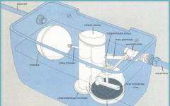
Let's start, as expected, by studying the instruction manual 2.424.005 R3 Rechargeable flashlight "Electronics V6-05". Inconsistencies begin immediately after a careful comparison of the electrical circuit diagram (Fig. 1) and the design of the flashlight. In the circuit, the plus comes from the battery, and the minus is connected to the HL1 light bulb.

In reality, the coaxial terminal HL1 is permanently connected to the plus of the battery, and the minus is connected through S1 to the threaded socket. Having carefully examined the installation connections, we immediately notice that HL1 is not connected according to the diagram, capacitor C1 is not connected to VD1 and VD2, as shown in Fig. 1, but to the elastic contact of the structure, pressing the minus battery, which is structurally and technologically convenient, since C1, as the largest element, it is quite rigidly mounted with structural elements - one of the pins of the power plug, structurally combined with the ACF housing and the battery spring contact; resistor R2 is not connected in series with capacitor C1, but is soldered with one end to the second pin of the power plug, and the other to the holder. U1. This is also not taken into account in the ACF scheme in . The remaining connections correspond to the diagram shown in Fig. 2.

But if you do not take into account the design and technological advantages, which are quite obvious, then in principle it does not matter how C1 is connected, according to Fig. 1 or Fig. 2. By the way, with a good idea to refine the AKF charger circuit, it was not possible to avoid the use of “extra” elements.
The memory circuit, while maintaining the general algorithm, can be significantly simplified by assembling it according to Fig. 3.

The difference is that elements VD1 and VD2 in the diagram in Fig. 3 perform two functions, which made it possible to reduce the number of elements. Zener diode VD1 for the negative half-wave of the supply voltage on VD1, VD2 serves as a rectifier diode, it is also a source of positive reference voltage for the comparison circuit (CC), the (second) function of which is also performed by VD2. CC works as follows: when the EMF value at the cathode VD2 is less than the voltage at its anode, the normal process of charging the battery occurs. As the battery charges, the EMF value on the battery increases, and when it reaches the voltage at the anode, VD2 will close and the charge will stop. The value of the reference voltage VD1 (stabilization voltage) must be equal to the sum of the voltage drop in the forward direction across VD2 + voltage drop across R3VD3 + battery emf and is selected for a specific charge current and specific elements. The emf of a fully charged disk is 1.35 V.
With this charging scheme, the LED, as an indicator of the battery charge state, lights up brightly at the beginning of the process, as it charges, its brightness decreases, and when it reaches full charge, it goes out. If during operation it is noticed that the product of the charge current and the glow time of VD3 in hours is significantly less than the value of its theoretical capacity, then this does not indicate that the comparator on VD2 is not working correctly, but that one or more disks have insufficient capacity.
terms of Use
Now let's analyze the charge and discharge of the battery. According to specifications (12MO.081.045), the charging time for a completely discharged battery at a voltage of 220 V is 20 hours. The charging current at C1 = 0.5 μF, taking into account the spread in capacity and fluctuations in the supply voltage, is about 25-28 mA, which corresponds to the recommendations, and The recommended discharge current is twice the charging current, i.e. 50
mA. The number of complete charge-discharge cycles is 392. In a real ACF design, the discharge is carried out on a standard 3.5 V x 0.15 A light bulb (with three disks), although it gives an increase in brightness, but also due to an increase in current from the battery in excess of that recommended by the specifications , negatively affects the service life of the battery, so such a replacement is hardly advisable, since in some copies of the disks this can cause increased gas formation, which in turn will lead to an increase in pressure inside the housing and to a deterioration in the internal contact made by the disc spring between the tablet package active substance and the minus part of the body. This also leads to the release of electrolyte through the seal, causing corrosion and associated deterioration of contact both between the disks themselves and between the disks and the metal elements of the AKF structure.
In addition, due to leakage, water evaporates from the electrolyte, resulting in an increase in the internal resistance of the disk and the entire battery. With further operation of such a disk, it completely fails as a result of the conversion of the electrolyte partly into crystalline KOH, partly into potash K2CO3. It is for these reasons that special attention must be paid to charge-discharge issues.
Practical repair
So, one of the three batteries has gone bad. You can assess its condition with an Avometer. To do this (in the appropriate polarity), each disk is briefly short-circuited with the probes of an avometer set to measure direct current within 2-2.5 A.
For good, freshly charged disks, the short-circuit current should be within 2-3 A. When repairing an ACF, two logical options may arise: 1) there are no spare disks; 2) there are spare disks.
In the first case, this solution will be the simplest. Instead of the third, unusable disk, a washer is installed from the copper body of an unusable transistor of the KT802 type, which, moreover, fits well in size into most AKF designs. To make a washer, remove the terminals of the transistor electrodes and clean both ends with a fine file from the coating until copper appears, then they are ground on fine-grained sanding paper laid on a flat plane, after which they are polished to a shine on a piece of felt with an applied layer of GOI paste. All these operations are necessary to reduce the influence of contact resistance on the combustion time. The same applies to the contact ends of the disks, the darkened surfaces of which during operation are desirable to be sanded for the same reasons.
Since removing one disk will lead to a decrease in the brightness of the HL1 glow, a 2.5 V light bulb at 0.15 A is installed in the AKF or, even better, a 2.5 V light bulb at 0.068 A, which, although it has less power, reduces the current discharge makes it possible to bring it closer to that recommended by the specifications, which will have a beneficial effect on the life of the battery disks. Practical disassembly and analysis of correctable causes of disk failure showed that quite often the cause of failure is the destruction of the disc spring. Therefore, do not rush to throw away an unusable disk and, if you are lucky, you can make it work some more. This operation will require sufficient accuracy and certain plumbing skills.
To carry it out, you will need a small bench vice, a ball from a ball bearing with a diameter of about 10 mm and a smooth steel plate 3-4 mm thick. The plate is placed through a 1mm thick electrical cardboard gasket between the jaws and the positive part of the body, and the ball is placed between the second jaw and the negative part of the body, orienting the ball approximately at its center. The electrical cardboard gasket is designed to eliminate short circuits of the disk, and the plate is designed to uniformly distribute the force and prevent deformation of the positive part of the battery case from notching on the jaws of the vice. Their size is obvious. Gradually tighten the vice. Having pressed the ball 1-2 mm, remove the disk from the device and control the short-circuit current. Usually, after one or two clamps, more than half of the charged disks begin to show an increase in short-circuit current up to 2-2.5 A. After a certain stroke, the clamping force increases sharply, which means that the deformable part of the housing rests on the tablet. Further pressing is impractical, since it leads to destruction of the battery. If after the stop the short-circuit current does not increase, then the disk is completely unusable.
In the second case, simply replacing the disk with another one may also not bring the desired result, since fully functional disks have so-called “capacitive” memory.
Due to the fact that when operating in a battery, there is always at least one disk that has less than the capacity value, which is why when it is discharged, the internal resistance sharply increases, which limits the possibility of complete discharge of the remaining disks. It is not advisable to subject such a battery to some recharging to eliminate this phenomenon, since this will not lead to an increase in capacity, but only to failure of the best drives. Therefore, when replacing at least one disk in a battery, it is advisable to subject them all to forced training (give one full charge-discharge cycle) to eliminate the above phenomena. The charge of each disk is carried out in the same ACF, using washers made of transistors instead of two disks.
The discharge is carried out on a resistor with a resistance of 50 Ohms, providing a discharge current of 25 mA (which corresponds to the specifications), until the voltage across it reaches 1 V. After this, the disks are combined into a battery and charged together. Having charged the entire battery, discharge it to the standard HL until the battery reaches 3 V. Under a load of the same HL, check the short-circuit current of each disk discharged to 1 V again.
For disks suitable for operation as part of a battery, the short-circuit current of each disk should be approximately the same. The battery capacity can be considered sufficient for practical use if the discharge time to 3 V is 30-40 minutes.
Details
Fuse.U1. Having observed the evolution of ACF circuitry during repairs for about two decades, it was noticed that in the mid-80s, some enterprises began to produce batteries without fuses with a current-limiting resistor of 0.5 W and a resistance of 150-180 Ohms, which is quite justified, since in the event of a breakdown The C1 role. U1 was played by R2 (Fig. 1) or R2 (Fig. 2 and 3), the conductive layer of which evaporated much earlier (than U1 burned at 0.15 A), interrupting the circuit, which is what is required from the fuse. Practice confirms that if a current-limiting resistor with a power of 0.5 W in a real ACF circuit heats up noticeably, then this clearly indicates a significant leakage C1 (which is difficult to determine with an avometer, and also due to changes in its value over time), and it must be replaced .
Capacitor C1 type MBM 0.5 μF at 250 V is the most unreliable element. It is designed for use in DC circuits with the appropriate voltage, and the use of such capacitors in AC networks, when the voltage amplitude in the network can reach 350 V, and taking into account the presence in the network of numerous peaks from inductive loads, as well as the charging time of a completely discharged ACF according to the specifications (about 20 hours), then its reliability as a radio element becomes very low. The most reliable capacitor, which has optimal dimensions that allow it to fit into ACFs of various design sizes, is the capacitor K42U-2 0.22 μF Ch 630 V or even K42U 0.1 μF Ch 630 V. Reducing the charging current to approximately 15-18 mA, at 0.22 μF and up to 8-10 mA at 0.1 μF, practically only causes an increase in its charging time, which is not significant.
LED indicator of charging current VD3. In ACFs that do not have an LED indicator of the charge current, it can be installed by connecting it to the open circuit at point A (Fig. 2).
The LED is connected in parallel with the measuring resistor R3 (Fig. 4), which must be selected when making a new one or reducing C1. With capacitance C1 equal to 0.22 μF instead of 0.5 μF, the brightness of VD3 will decrease, and at 0.1 μF VD3 may not light up at all. Therefore, taking into account the above charge currents, in the first case, resistor R3 must be increased in proportion to the decrease in current, and in the second case, it must be removed completely. In practice, taking into account the fact that working with 220 V is very unsafe, it is better to select the resistance R3 by connecting an adjustable direct current source (RIPS) through a milliammeter to point B (Fig. 3), and controlling the charge current. Instead of R3, a potentiometer with a resistance of 1 kOhm is temporarily connected, turned on by a rheostat to the minimum resistance. By increasing the RIPT voltage, the battery charging current is set to 25 mA.

Without changing the set voltage of the RIPT, connect the milliammeter to the open circuit VD3 at point C and, gradually increasing the resistance of the potentiometer, achieve a current through it of 10 mA, i.e. half of the maximum for AL307. This point is especially important for circuits without a zener diode, in which, at the first moment after switching on when charging C1, the current through VD3 can become large, despite the presence of a current-limiting resistor R1, and can lead to VD3 failure. In steady state, R1 has virtually no effect on the charge current due to its low resistance compared to the reactive (about 9 kOhm) resistance C1. When modifying, VD3 is installed in a hole with a diameter of 5 mm, drilled symmetrically to the parting line in the housing between the supports of the spring contact connected to the coaxial terminal HL1 and the battery positive. The measuring resistor is placed there.
Rectifier diodes
Considering the presence of a current surge during the initial charge of C1, to increase reliability in the AKF rectifier, it is advisable to use any silicon pulse diodes with a reverse voltage of 30 V or more.
Non-standard use of ACF
By making an adapter from the base of an unusable light bulb and the power connector of a radio receiver, the AKF can be used not only as a light source, but also as a source of secondary power supply with a voltage of 3.75 V. At an average volume level (consumption current 20-25 mA), its capacity is quite sufficient for listening to VEF for several hours.
In some cases, in the absence of electricity, the ACF can be recharged from a radio broadcast line. Owners of AKF with an LED indicator can observe the process of dynamic blinking of the LED. VD3 burns especially smoothly from “heavy” rock, so if you don’t like listening, charge the ACF, use the energy for peaceful purposes. The physical meaning of this phenomenon is that reactance decreases with increasing frequency, therefore, at a significantly lower voltage (15-30 V), the pulsed value of the charge current through the indicator is sufficient for it to glow and, naturally, recharge.
Literature:
- Vuzetsky V.N. Charger for a rechargeable flashlight // Radioamator. - 1997. - No. 10. - P. 24.
- Tereshchuk R.M. and others. Semiconductor receiving and amplifying devices: Reference. radio amateur. - Kyiv: Nauk. Dumka, 1988
Read and write useful
As a sample, let's take a rechargeable flashlight from the company "DiK", "Lux" or "Cosmos" (see photo). This pocket flashlight is small-sized, comfortable in the hand and has a fairly large reflector - 55.8 mm in diameter, the LED matrix of which has 5 white LEDs, which provides a good and large illumination spot.
In addition, the shape of the flashlight is familiar to everyone, and many from childhood, in a word - a brand. The charger is located inside the flashlight itself; you just need to remove the back cover and plug it into a power outlet. But nothing stands still and this flashlight design has also undergone changes, especially its internal filling. The latest model at the moment is DIK AN 0-005 (or DiK-5 EURO).
Earlier versions are DIK AN 0-002 and DIK AN 0-003, differing in that they contained disk batteries (3 pcs), Ni-Cd series D-025 and D-026, with a capacity of 250 mA/h, or model AN 0-003 - assembly of newer D-026D batteries with a higher capacity, 320 mAh and incandescent light bulbs of 3.5 or 2.5 V, with a current consumption of 150 and 260 mA, respectively. An LED, for comparison, consumes about 10 mA and even a matrix of 5 pieces is 50 mA.
Of course, with such characteristics, the flashlight could not shine for a long time; it lasted for a maximum of 1 hour, especially the first models.
What is it about the latest flashlight model DIK AN 0-005?
Well, firstly, there is an LED matrix of 5 LEDs, as opposed to 3 or an incandescent light bulb, which gives significantly more light with lower current consumption, and secondly, the flashlight costs only 1 1.2-inch modern Ni-MH battery -1.5 V and capacity from 1000 to 2700 mAh.
Some will ask, how can a 1.2 V AA battery “light up” the LEDs, because for them to shine brightly you need about 3.5 V? For this reason, in earlier models they placed 3 batteries in series and received 3.6 V.
But I don’t know who first came up with the idea, the Chinese or someone else, to make a voltage converter (multiplier) from 1.2 V to 3.5 V. The circuit is simple, in Chinese flashlights there are only 2 parts - a resistor and a similar radio component to a transistor marked - 8122 or 8116, or SS510, or SK5B. SS510 is a Schottky diode.
Such a flashlight shines well, brightly, and what is not unimportant - for a long time, and the charge-discharge cycles are not 150, as in previous models, but much more, which increases the service life several times. But!! In order for an LED flashlight to serve for a long time, you need to insert it into a 220 V outlet when it is turned off! If this rule is not followed, then when charging you can easily burn out the Schottky diode (SS510), and often the LEDs at the same time.
I once had to repair a DIK AN 0-005 flashlight. I don’t know exactly what caused it to fail, but I assume that they plugged it into an outlet and forgot it for several days, although according to the passport it should be charged for no more than 20 hours. In short, the battery failed, leaked, and 3 out of 5 LEDs burned out, plus the converter (diode) also stopped working.
I had a 2700 mAh AA battery, left over from an old camera, as well as LEDs, but finding the part - SS510 (Schottky diode) - turned out to be problematic. This LED flashlight is most likely of Chinese origin and such a part can probably only be bought there. And then I decided to make a voltage converter from the parts that I had, i.e. from domestic ones: transistor KT315 or KT815, high-voltage transformer and others (see diagram).

The circuit is not new, it has existed for a long time, I just used it in this flashlight. True, instead of 2 radio components, like the Chinese, I got 3, but they were free.
The electrical circuit, as you can see, is elementary; the most difficult thing is to wind the RF transformer on a ferrite ring. The ring can be used from an old switching power supply, from a computer, or from an energy-saving non-working light bulb (see photo).

The outer diameter of the ferrite ring is 10-15 mm, thickness is approximately 3-4 mm. It is necessary to wind 2 windings of 30 turns each with a wire of 0.2-0.3 mm, i.e. we first wind 30 turns, then make a tap from the middle and another 30. If you take a ferrite ring from the board of a fluorescent light bulb, it is better to use 2 pieces, folded them together. The circuit will also work on one ring, but the glow will be weaker.
I compared 2 flashlights for glow, the original (Chinese) and the one converted according to the above scheme - I saw almost no difference in brightness. By the way, the converter can be inserted not only into a rechargeable flashlight, but also into a regular one that runs on batteries, then it will be possible to power it with just 1 1.5 V battery.

The flashlight charger circuit has undergone almost no changes, with the exception of the ratings of some parts. Charging current is approximately 25 mA. When charging, the flashlight must be turned off! And do not press the switch while charging, since the charging voltage is more than 2 times higher than the battery voltage, and if it goes to the converter and is amplified, the LEDs will have to be partially or completely changed...
In principle, according to the above diagram, you can easily make an LED flashlight with your own hands, by mounting it, for example, in the body of some old, even the most ancient flashlight, or you can make the body yourself.

And in order not to change the structure of the switch of the old flashlight, which used a small 2.5-3.5 V incandescent light bulb, you need to break the already burnt out light bulb and solder 3-4 white LEDs to the base, instead of the glass bulb.
And also, for charging, install a connector under the power cord from an old printer or receiver. But, I want to draw your attention, if the flashlight body is metal, do not mount the charger there, but make it remote, i.e. separately. It is not at all difficult to remove the AA battery from the flashlight and insert it into the charger. And don’t forget to insulate everything well! Especially in places where there is a voltage of 220 V.
I think that after the conversion, the old flashlight will serve you for many more years...
Despite the wide selection of LED flashlights of various designs in stores, radio amateurs are developing their own versions of circuits for powering white super-bright LEDs. Basically, the task comes down to how to power an LED from just one battery or accumulator, and conduct practical research.
After a positive result is obtained, the circuit is disassembled, the parts are put into a box, the experiment is completed, and moral satisfaction sets in. Often research stops there, but sometimes the experience of assembling a specific unit on a breadboard turns into a real design, made according to all the rules of art. Below we consider several simple circuits developed by radio amateurs.
In some cases, it is very difficult to determine who is the author of the scheme, since the same scheme appears on different sites and in different articles. Often the authors of articles honestly write that this article was found on the Internet, but it is unknown who published this diagram for the first time. Many circuits are simply copied from the boards of the same Chinese flashlights.
Why are converters needed?
The thing is that the direct voltage drop is, as a rule, no less than 2.4...3.4V, so it is simply impossible to light an LED from one battery with a voltage of 1.5V, and even more so from a battery with a voltage of 1.2V. There are two ways out here. Either use a battery of three or more galvanic cells, or build at least the simplest one.
It is the converter that will allow you to power the flashlight with just one battery. This solution reduces the cost of power supplies, and in addition allows for fuller use: many converters are operational with a deep battery discharge of up to 0.7V! Using a converter also allows you to reduce the size of the flashlight.
The circuit is a blocking oscillator. This is one of the classic electronic circuits, so if assembled correctly and in good working order, it starts working immediately. The main thing in this circuit is to wind transformer Tr1 correctly and not to confuse the phasing of the windings.

As a core for the transformer, you can use a ferrite ring from an unusable board. It is enough to wind several turns of insulated wire and connect the windings, as shown in the figure below.

The transformer can be wound with winding wire such as PEV or PEL with a diameter of no more than 0.3 mm, which will allow you to place a slightly larger number of turns on the ring, at least 10...15, which will somewhat improve the operation of the circuit.
The windings should be wound into two wires, then connect the ends of the windings as shown in the figure. The beginning of the windings in the diagram is shown by a dot. You can use any low-power n-p-n transistor: KT315, KT503 and the like. Nowadays it is easier to find an imported transistor such as BC547.
If you don’t have an n-p-n transistor at hand, you can use, for example, KT361 or KT502. However, in this case you will have to change the polarity of the battery.
Resistor R1 is selected based on the best LED glow, although the circuit works even if it is simply replaced with a jumper. The above diagram is intended simply “for fun”, for conducting experiments. So after eight hours of continuous operation on one LED, the battery drops from 1.5V to 1.42V. We can say that it almost never discharges.
To study the load capacity of the circuit, you can try connecting several more LEDs in parallel. For example, with four LEDs the circuit continues to operate quite stably, with six LEDs the transistor begins to heat up, with eight LEDs the brightness drops noticeably and the transistor gets very hot. But the scheme still continues to work. But this is only for scientific research, since the transistor will not work for a long time in this mode.
If you plan to create a simple flashlight based on this circuit, you will have to add a couple more parts, which will ensure a brighter glow of the LED.

It is easy to see that in this circuit the LED is powered not by pulsating, but by direct current. Naturally, in this case the brightness of the glow will be slightly higher, and the level of pulsations of the emitted light will be much less. Any high-frequency diode, for example, KD521 (), will be suitable as a diode.
Converters with choke
Another simplest diagram is shown in the figure below. It is somewhat more complicated than the circuit in Figure 1, it contains 2 transistors, but instead of a transformer with two windings it only has inductor L1. Such a choke can be wound on a ring from the same energy-saving lamp, for which you will need to wind only 15 turns of winding wire with a diameter of 0.3...0.5 mm.

With the specified inductor setting on the LED, you can get a voltage of up to 3.8V (forward voltage drop across the 5730 LED is 3.4V), which is enough to power a 1W LED. Setting up the circuit involves selecting the capacitance of capacitor C1 in the range of ±50% of the maximum brightness of the LED. The circuit is operational when the supply voltage is reduced to 0.7V, which ensures maximum use of battery capacity.
If the considered circuit is supplemented with a rectifier on diode D1, a filter on capacitor C1, and a zener diode D2, you will get a low-power power supply that can be used to power op-amp circuits or other electronic components. In this case, the inductance of the inductor is selected within the range of 200...350 μH, diode D1 with a Schottky barrier, zener diode D2 is selected according to the voltage of the supplied circuit.

With a successful combination of circumstances, using such a converter you can obtain an output voltage of 7...12V. If you plan to use the converter to power only LEDs, zener diode D2 can be excluded from the circuit.
All the considered circuits are the simplest voltage sources: limiting the current through the LED is carried out in much the same way as is done in various key fobs or in lighters with LEDs.
The LED, through the power button, without any limiting resistor, is powered by 3...4 small disk batteries, the internal resistance of which limits the current through the LED to a safe level.
Current Feedback Circuits
But an LED is, after all, a current device. It is not for nothing that the documentation for LEDs indicates direct current. Therefore, true LED power circuits contain current feedback: once the current through the LED reaches a certain value, the output stage is disconnected from the power supply.
Voltage stabilizers work exactly the same way, only there is voltage feedback. Below is a circuit for powering LEDs with current feedback.

Upon closer examination, you can see that the basis of the circuit is the same blocking oscillator assembled on transistor VT2. Transistor VT1 is the control one in the feedback circuit. Feedback in this scheme works as follows.
LEDs are powered by voltage that accumulates across an electrolytic capacitor. The capacitor is charged through a diode with pulsed voltage from the collector of transistor VT2. The rectified voltage is used to power the LEDs.
The current through the LEDs passes along the following path: the positive plate of the capacitor, LEDs with limiting resistors, the current feedback resistor (sensor) Roc, the negative plate of the electrolytic capacitor.
In this case, a voltage drop Uoc=I*Roc is created across the feedback resistor, where I is the current through the LEDs. As the voltage increases (the generator, after all, works and charges the capacitor), the current through the LEDs increases, and, consequently, the voltage across the feedback resistor Roc increases.
When Uoc reaches 0.6V, transistor VT1 opens, closing the base-emitter junction of transistor VT2. Transistor VT2 closes, the blocking generator stops, and stops charging the electrolytic capacitor. Under the influence of a load, the capacitor is discharged, and the voltage across the capacitor drops.
Reducing the voltage on the capacitor leads to a decrease in the current through the LEDs, and, as a result, a decrease in the feedback voltage Uoc. Therefore, transistor VT1 closes and does not interfere with the operation of the blocking generator. The generator starts up and the whole cycle repeats again and again.
By changing the resistance of the feedback resistor, you can vary the current through the LEDs within a wide range. Such circuits are called pulse current stabilizers.
Integral current stabilizers
Currently, current stabilizers for LEDs are produced in an integrated version. Examples include specialized microcircuits ZXLD381, ZXSC300. The circuits shown below are taken from the DataSheet of these chips.

The figure shows the design of the ZXLD381 chip. It contains a PWM generator (Pulse Control), a current sensor (Rsense) and an output transistor. There are only two hanging parts. These are LED and inductor L1. A typical connection diagram is shown in the following figure. The microcircuit is produced in the SOT23 package. The generation frequency of 350KHz is set by internal capacitors; it cannot be changed. The device efficiency is 85%, starting under load is possible even with a supply voltage of 0.8V.

The forward voltage of the LED should be no more than 3.5V, as indicated in the bottom line under the figure. The current through the LED is controlled by changing the inductance of the inductor, as shown in the table on the right side of the figure. The middle column shows the peak current, the last column shows the average current through the LED. To reduce the level of ripple and increase the brightness of the glow, it is possible to use a rectifier with a filter.

Here we use an LED with a forward voltage of 3.5V, a high-frequency diode D1 with a Schottky barrier, and a capacitor C1 preferably with a low equivalent series resistance (low ESR). These requirements are necessary in order to increase the overall efficiency of the device, heating the diode and capacitor as little as possible. The output current is selected by selecting the inductance of the inductor depending on the power of the LED.
It differs from the ZXLD381 in that it does not have an internal output transistor and a current sensor resistor. This solution allows you to significantly increase the output current of the device, and therefore use a higher power LED.

An external resistor R1 is used as a current sensor, by changing the value of which you can set the required current depending on the type of LED. This resistor is calculated using the formulas given in the datasheet for the ZXSC300 chip. We will not present these formulas here; if necessary, it is easy to find a datasheet and look up the formulas from there. The output current is limited only by the parameters of the output transistor.
When you turn on all the described circuits for the first time, it is advisable to connect the battery through a 10 Ohm resistor. This will help avoid the death of the transistor if, for example, the transformer windings are incorrectly connected. If the LED lights up with this resistor, then the resistor can be removed and further adjustments can be made.
Boris Aladyshkin